
Electrical

About the Electrical PCB
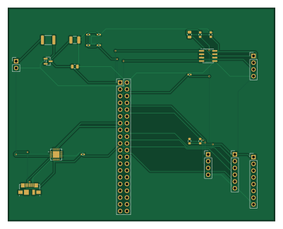
Electrical is an open source Raspberry Pi PCB design by engineering-with-ai, published on GitHub. It is a 2-layer board measuring 100 × 80 mm, with 24 components from 17 distinct parts.
Its main chip is the CM4, from the Raspberry Pi family. Other key parts include the MAX3485 and CP2102N. By type, the board carries 8 capacitors, 7 connectors, 5 resistors, 2 ICs, 1 transistor and 1 fuse.
It belongs with the power & battery designs in this gallery.
From the project
Electrical base template — validation gates, simulation harness, agent system prompt
CM4 carrier board — Raspberry Pi Compute Module 4 carrier for an outdoor self-contained sensor system with computer vision, thermal imaging, cellular uplink, and solar + battery power. 5V screw terminal input, polyfuse + reverse polarity protection, CP2102N USB-UART debug, MAX3485 RS-485, I2C/SPI/GPIO headers on 2.54mm pitch, 100x80mm 2-layer board.
Foundation board that exposes raw CM4 interfaces via headers. Downstream boards connect RGB camera (CSI), FLIR Lepton thermal sensor (SPI), cellular modem (RS-485 Modbus), and solar charge controller (I2C BMS telemetry).
Main components on the Electrical
Electrical bill of materials (BOM)
24 components, 17 distinct parts — part numbers from the project's BOM.
| Qty | Part | Footprint | Refs |
|---|---|---|---|
| 1 | MAX3485 | SOIC-8_3.9x4.9mm_P1.27mm | U1 |
| 1 | CP2102N | QFN-20-1EP_4x4mm_P0.5mm_EP2.5x2.5mm | U2 |
| 1 | SI2301 | SOT-23 | Q1 |
| 1 | 5V_IN | PinHeader_1x02_P2.54mm_Vertical | J1 |
| 1 | CM4 | PinHeader_2x20_P2.54mm_Vertical | J2 |
| 1 | RS485 | PinHeader_1x04_P2.54mm_Vertical | J3 |
| 1 | USB_DEBUG | USB_Micro-B_Molex_47346-0001 | J4 |
| 1 | I2C | PinHeader_1x04_P2.54mm_Vertical | J5 |
| 1 | SPI | PinHeader_1x06_P2.54mm_Vertical | J6 |
| 1 | GPIO | PinHeader_1x08_P2.54mm_Vertical | J7 |
| 1 | 2A | Fuse_1812_4532Metric | F1 |
| 1 | 100UF 100uF | C_1210_3225Metric | C1 |
| 1 | 10UF 10uF | C_0805_2012Metric | C2 |
| 6 | 100NF 100nF | C_0402_1005Metric | C3, C4, C5, C6, C7, C8 |
| 1 | 120 | R_0805_2012Metric | R1 |
| 2 | 560 | R_0603_1608Metric | R2, R3 |
| 2 | 2.2K 2.2k | R_0603_1608Metric | R4, R5 |
Electrical design files
The KiCad project lives in the engineering-with-ai/electrical-pcb repository on GitHub; these links point at the commit this page was built from.
- Layoutcad/cm4_carrier.kicad_pcb
- Schematiccad/cm4_carrier.kicad_sch
- BOMoutput/fab/bom.csv
Electrical: common questions
What microcontroller does the Electrical use?
The Electrical is built around the CM4, from the Raspberry Pi family.
How big is the Electrical PCB?
The Electrical measures 100 × 80 mm, has 2 copper layers and is 1.6 mm thick.
How many components are on the Electrical?
24 components, from 17 distinct parts, with part numbers taken from the project's own BOM. The full bill of materials is listed on this page.
Where can I download the Electrical design files?
From the engineering-with-ai/electrical-pcb repository on GitHub, which has the KiCad layout, the schematic and the BOM; the links under Design files point to each one.
Can I use the Electrical design in my own project?
The repository has no license, so all rights stay with engineering-with-ai. Use it as a reference, and ask the author before reusing the design.
Can I test firmware for the Electrical without the hardware?
Yes. HardLabs builds a simulation of the board from its netlist and BOM, so you can run and debug Raspberry Pi firmware against it before you order a PCB.
Similar boards
 Raspberry Pi
Open source rover
nasa-jpl
220 × 178 mm144 parts2LApache-2.09.7k Raspberry Pi
SPIRIT
SPIRIT-org
82 × 155 mm130 parts6LCERN-OHL-S-2.01.3k Raspberry Pi
CM5RevEng
schlae
55 × 40 mm417 parts10LNo license1.0k Raspberry Pi
Haxo hw
cardonabits
102.4 × 211.3 mm38 parts2LCustom license672 Raspberry Pi
PowerBook
BlueSCSI
74.5 × 56.3 mm78 parts2LGPL-3.0449 Raspberry Pi
Desktop 50 Pin TopConn
89.2 × 82.6 mm103 parts2LGPL-3.0449