
Lt3014-test

About the Lt3014-test PCB
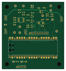
Lt3014-test is an open source RP2040/RP2350 PCB design by eshazen, published on GitHub. It is a 4-layer board measuring 64.8 × 69.9 mm, with 51 components from 43 distinct parts.
Its main chip is the RaspberryPi_Pico, from the RP2040/RP2350 family. Other key parts include the AD7380BCPZ-RL7 and ADA4940-2ACPZ-R7. By type, the board carries 18 resistors, 10 test points, 6 capacitors, 5 connectors, 4 diodes and 3 ICs.
From the project
Power supplies and electronics for SiPM base optodes
This is a test board to provide the following features. It is intended to take as input ~65V bulk power from BZ's boost converter.
The final version would be stripped down to minimal parts and small package sizes to fit on a future version of the detector adapter board.
LT3014 high voltage regulator, programmable from 32-62V using a digital pot INA121 current sense / trip circuit. Nominally set to trip at 10mA current but easy to change via resistor swap. Set up (hopefully) to power up in a tripped state (HV off) until the R-Pi turns on the power Ability to measure output voltage and load…
Main components on the Lt3014-test
Lt3014-test bill of materials (BOM)
51 components, 43 distinct parts — part numbers from the project's BOM.
| Qty | Part | Footprint | Refs |
|---|---|---|---|
| 1 | AD7380BCPZ-RL7 LT3014xS5 Analog Devices | SOT-23-5 | U1 |
| 1 | AD7380BCPZ-RL7 INA201 Analog Devices | SOIC-8_3.9x4.9mm_P1.27mm | U3 |
| 1 | ADA4940-2ACPZ-R7 AD5270 Analog Devices | MSOP-10_3x3mm_P0.5mm | U4 |
| 1 | RaspberryPi_Pico | RaspberryPi_Pico_Common_Unspecified | A1 |
| 3 | BSS138 | SOT-23 | Q3, Q4, Q5 |
| 1 | SHF-117-01-L-D-SM Conn_01x02 Samtec | PinHeader_1x02_P2.54mm_Vertical | J1 |
| 1 | M05X2_SMD_0.050_NOCREAM Conn_01x02 | PinHeader_1x02_P2.54mm_Vertical | J2 |
| 1 | M03X1_0.050_SMD_NO_CREAM Conn_01x02 | PinHeader_1x02_P2.54mm_Vertical | J3 |
| 1 | 10118194-0001LF Conn_01x08 Amphenol Communications Solutions | PinHeader_1x08_P2.54mm_Vertical | J4 |
| 1 | 15150402601000 Conn_01x04 HARTING Elektronik | PinHeader_1x04_P2.54mm_Vertical | J5 |
| 1 | Jumper_2_Open | PinHeader_1x02_P2.54mm_Vertical | JP1 |
| 1 | DPOT | tp_SMT_label2 | TP1 |
| 1 | VR_ADJ | tp_SMT_label2 | TP2 |
| 1 | VR_IN | tp_SMT_label2 | TP3 |
| 1 | OUTPUT | tp_SMT_label2 | TP4 |
| 1 | VIN60 | tp_SMT_label2 | TP5 |
| 1 | VSENSE | tp_SMT_label2 | TP6 |
| 1 | IMON | tp_SMT_label2 | TP7 |
| 1 | CMP | tp_SMT_label2 | TP8 |
| 2 | GND | tp_SMT_label2 | TP9, TP10 |
Show 23 more
| Qty | Part | Footprint | Refs |
|---|---|---|---|
| 2 | SBR1A20T5-7 LED Diodes Inc. | my_SMT_0603 | D1, D2 |
| 2 | LED | my_SMT_0603 | D3, D4 |
| 1 | GRM1555C1H102JA01D 1.0uF Murata | C_0603_1608Metric_Pad1.08x0.95mm_HandSolder | C4 |
| 1 | GRM1555C1H331JA01D 1.0uF Murata | C_0603_1608Metric_Pad1.08x0.95mm_HandSolder | C5 |
| 1 | CL05A105KP5NNNC 10nF Samsung | C_0603_1608Metric_Pad1.08x0.95mm_HandSolder | C6 |
| 1 | CL05A105KP5NNNC 1.0uF Samsung | C_0603_1608Metric_Pad1.08x0.95mm_HandSolder | C7 |
| 1 | GRM155R71H104KE14D 10nF Murata | C_0603_1608Metric_Pad1.08x0.95mm_HandSolder | C9 |
| 1 | GRM155R71H104KE14D ~ Murata | C_0603_1608Metric_Pad1.08x0.95mm_HandSolder | C10 |
| 1 | RR0510P-183-D 3.00 1% Susumu | R_0603_1608Metric_Pad0.98x0.95mm_HandSolder | R1 |
| 1 | RR0510P-222-D 2.50M 1% Susumu | R_0603_1608Metric_Pad0.98x0.95mm_HandSolder | R2 |
| 1 | CRCW040233R0FKEDC 50.0k 1% Vishay | R_0603_1608Metric_Pad0.98x0.95mm_HandSolder | R3 |
| 1 | RR0510P-183-D 4.7k Susumu | R_0603_1608Metric_Pad0.98x0.95mm_HandSolder | R4 |
| 1 | RR0510P-222-D 10.0k 1% Susumu | R_0603_1608Metric_Pad0.98x0.95mm_HandSolder | R5 |
| 2 | CRCW040233R0FKEDC 1.5k Vishay | R_0603_1608Metric_Pad0.98x0.95mm_HandSolder | R6, R17 |
| 1 | RR0510P-183-D 100k Susumu | R_0603_1608Metric_Pad0.98x0.95mm_HandSolder | R7 |
| 1 | RR0510P-222-D 1.5k Susumu | R_0603_1608Metric_Pad0.98x0.95mm_HandSolder | R8 |
| 1 | CRCW040233R0FKEDC 200k 1% Vishay | R_0603_1608Metric_Pad0.98x0.95mm_HandSolder | R9 |
| 2 | RR0510P-183-D 10.0k 1% Susumu | R_0603_1608Metric_Pad0.98x0.95mm_HandSolder | R10, R15 |
| 1 | RR0510P-222-D 210k Susumu | R_0603_1608Metric_Pad0.98x0.95mm_HandSolder | R11 |
| 1 | CRCW040233R0FKEDC 140k Vishay | R_0603_1608Metric_Pad0.98x0.95mm_HandSolder | R12 |
| 2 | RR0510P-183-D 0R Susumu | R_0603_1608Metric_Pad0.98x0.95mm_HandSolder | R13, R14 |
| 1 | RR0510P-222-D 100k Susumu | R_0603_1608Metric_Pad0.98x0.95mm_HandSolder | R16 |
| 1 | RR0510P-183-D 1.5k Susumu | R_0603_1608Metric_Pad0.98x0.95mm_HandSolder | R18 |
Lt3014-test design files
The KiCad project lives in the eshazen/ninjanirs-sipm repository on GitHub; these links point at the commit this page was built from.
Lt3014-test: common questions
What microcontroller does the Lt3014-test use?
The Lt3014-test is built around the RaspberryPi_Pico, from the RP2040/RP2350 family.
How big is the Lt3014-test PCB?
The Lt3014-test measures 64.8 × 69.9 mm, has 4 copper layers and is 1.6 mm thick.
How many components are on the Lt3014-test?
51 components, from 43 distinct parts, with part numbers taken from the project's own BOM. The full bill of materials is listed on this page.
Where can I download the Lt3014-test design files?
From the eshazen/ninjanirs-sipm repository on GitHub, which has the KiCad layout, the schematic and the BOM; the links under Design files point to each one.
Can I use the Lt3014-test design in my own project?
The repository has no license, so all rights stay with eshazen. Use it as a reference, and ask the author before reusing the design.
Can I test firmware for the Lt3014-test without the hardware?
Yes. HardLabs builds a simulation of the board from its netlist and BOM, so you can run and debug RP2040/RP2350 firmware against it before you order a PCB.
More boards in ninjanirs-sipm
Similar boards
 RP2040/RP2350
Open Book Abridged Edition
joeycastillo
85 × 115 mm29 parts2LCC-BY-SA-4.08.1k RP2040/RP2350
Corne
foostan
277.2 × 107.5 mm164 parts2LCC-BY-4.07.7k RP2040/RP2350
Corne
277.2 × 107.5 mm164 parts2LCC-BY-4.07.7k RP2040/RP2350
LogicAnalyzer
gusmanb
57 × 55.2 mm6 parts2LGPL-3.05.0k RP2040/RP2350
Jitx design
55.5 × 65 mm26 parts4LGPL-3.05.0k RP2040/RP2350
Main
google
98 × 71 mm102 parts2LApache-2.02.9k