
AAquad

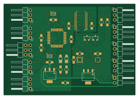
About the AAquad PCB
AAquad is an open source AVR/Arduino PCB design by Fberbari, published on GitHub under the GPL-3.0 license. It is a 2-layer board measuring 69.2 × 47.6 mm, with 37 components from 17 distinct parts.
Its main chip is the ATMEGA328-AU, from the AVR/Arduino family. Other key parts include the NC7SZ157P6X, L3GD20H, LIS3DHTR and SPX1117M3-L-1-5. By type, the board carries 10 capacitors, 8 LEDs, 7 ICs, 5 resistors, 2 transistors and 2 connectors.
It belongs with the sensors designs in this gallery.
From the project
(OUTDATED, see AAQuad-Evolution) a baremetal implementation of a multirotor flight computer.
This is an implementation of a quadcopter filght computer running baremetal on an atmega 328pb chip that takes input a standard hobby receiver and outputs pwm to esc's.
These directories contain the full firmware and the pcb design + gerber files.
As of right now, the system produces desirable results and has passed some basic functionality tests. I am currently waiting on a mechanical engineering student to finish designing the frame of the aircraft before further testing.
Main components on the AAquad
AAquad bill of materials (BOM)
37 components, 17 distinct parts.
| Qty | Part | Footprint | Refs |
|---|---|---|---|
| 2 | NC7SZ157P6X | SOT65P210X110-6N | IC1, IC2 |
| 1 | L3GD20H | LGA(3X3X1.0-16L) | IC3 |
| 1 | ATMEGA328-AU | TQFP-32_7x7mm_Pitch0.8mm | U1 |
| 1 | LIS3DHTR | VFLGA-16_3x3mm | U2 |
| 2 | SPX1117M3-L-1-5 | SOT230P700X180-3N | U3, U4 |
| 2 | BSS138 | SOT-23 | Q1, Q2 |
| 1 | programmer | Pin_Header_Angled_2x03_Pitch2.54mm | J1 |
| 1 | Conn_01x02 | Pin_Header_Angled_1x02_Pitch2.54mm | J2 |
| 1 | PCA9685PW_112 | TSSOP-28_W4.40mm | PWMdriver1 |
| 8 | Conn_01x03 | Pin_Header_Angled_1x03_Pitch2.54mm | aileron(horitz)1, elevator(vert)1, motor1, motor2, motor3, motor4, rudder(yaw)1, throttle1 |
| 1 | green | LED_0805_HandSoldering | D1 |
| 1 | red | LED_0805_HandSoldering | D2 |
| 7 | 0.1uF | C_0805_HandSoldering | C1, C3, C4, C5, C7, C10, C11 |
| 2 | 10uF | C_0805_HandSoldering | C6, C8 |
| 1 | 10nF | C_0805_HandSoldering | C9 |
| 2 | 300 | R_0805_HandSoldering | R1, R2 |
| 3 | 10K | R_0805_HandSoldering | R3, R4, R5 |
AAquad design files
The KiCad project lives in the Fberbari/AAquad repository on GitHub; these links point at the commit this page was built from.
AAquad: common questions
What microcontroller does the AAquad use?
The AAquad is built around the ATMEGA328-AU, from the AVR/Arduino family.
How big is the AAquad PCB?
The AAquad measures 69.2 × 47.6 mm, has 2 copper layers and is 1.6 mm thick.
How many components are on the AAquad?
37 components, from 17 distinct parts. The full bill of materials is listed on this page.
Where can I download the AAquad design files?
From the Fberbari/AAquad repository on GitHub, which has the KiCad layout; the links under Design files point to each one.
Can I use the AAquad design in my own project?
Yes, under the terms of its GPL-3.0 license, which Fberbari chose for the repository.
Can I test firmware for the AAquad without the hardware?
Yes. HardLabs builds a simulation of the board from its netlist and BOM, so you can run and debug AVR/Arduino firmware against it before you order a PCB.
Similar boards
 AVR/Arduino
Magspoof
samyk
35 × 29 mm11 parts2LNo license4.2k AVR/Arduino
Redox keyboard
mattdibi
162.2 × 126.5 mm77 parts2LMIT2.0k AVR/Arduino
Labrador
espotek-org
36.8 × 34.7 mm75 parts2LNo license1.2k AVR/Arduino
V4
stuartpittaway
30 × 50 mm38 parts2LCC-BY-NC-4.01.1k AVR/Arduino
ModuleV450
30 × 61.4 mm39 parts2LCC-BY-NC-4.01.1k AVR/Arduino
Discipline
coseyfannitutti
304.9 × 122.8 mm170 parts2LCC-BY-NC-4.01.0k