
PC-Link-Bridge PCB-and software

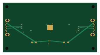
About the PC-Link-Bridge PCB-and software
PC-Link-Bridge PCB-and software is an open source RP2040/RP2350 PCB design by fikruyenialem-cpu, published on GitHub. It is a 4-layer board measuring 85 × 45 mm, with 8 components from 7 distinct parts.
Its main chip is the RP2040, from the RP2040/RP2350 family. Other key parts include the FT232HL-REEL and AP2112K-3.3TRG1. By type, the board carries 4 ICs, 2 connectors and 2 diodes.
It belongs with the usb & debug tools designs in this gallery.
From the project
Hardware Revision: v1.0 Author: Hardware Systems Engineering Team Design Environment: KiCad 8.0 / KiCad 7.0 Compatible Workspace Path: C:\pc-usb-bridge Milestone Status: HARDWARE & PCB DESIGN COMPLETE (AWAITING REVIEW BEFORE WINDOWS SOFTWARE PHASE)
Hardware Revision: v1.0 Author: Hardware Systems Engineering Team Design Environment: KiCad 8.0 / KiCad 7.0 Compatible Workspace Path: C:\pc-usb-bridge Milestone Status: HARDWARE & PCB DESIGN COMPLETE (AWAITING REVIEW BEFORE WINDOWS SOFTWARE PHASE)
this project provides a production grade, manufacturable hardware solution to bridge two personal computers (PC A and PC B) through standard USB Type-A ports. It enables bidirectional high-speed file transfer up to USB 2.0 High-Speed signaling (480 Mbps) while maintaining strict, hardware-enforced electrical power isolation between the two host…
Main components on the PC-Link-Bridge PCB-and software
PC-Link-Bridge PCB-and software bill of materials (BOM)
8 components, 7 distinct parts — part numbers from the project's BOM.
| Qty | Part | Footprint | Refs |
|---|---|---|---|
| 1 | RP2040 Raspberry Pi Ltd | QFN-56-1EP_7x7mm_P0.4mm_EP5.6x5.6mm | U1 |
| 1 | FT232HL-REEL FT232HL_A FTDI Chip | LQFP-48_7x7mm_P0.5mm | U2 |
| 1 | FT232HL-REEL FT232HL_B FTDI Chip | LQFP-48_7x7mm_P0.5mm | U3 |
| 1 | AP2112K-3.3TRG1 AP2112K-3.3 Diodes Incorporated | SOT-23-5 | U7 |
| 1 | GSB19111KEU USB_A_PORT_A Amphenol Commercial | USB_A_Molex_67643_Horizontal | J1 |
| 1 | GSB19111KEU USB_A_PORT_B Amphenol Commercial | USB_A_Molex_67643_Horizontal | J2 |
| 2 | PMEG3020EP Nexperia | D_SOD-128 | D1, D2 |
PC-Link-Bridge PCB-and software design files
The KiCad project lives in the fikruyenialem-cpu/PC-Link-Bridge_PCB-and_software repository on GitHub; these links point at the commit this page was built from.
PC-Link-Bridge PCB-and software: common questions
What microcontroller does the PC-Link-Bridge PCB-and software use?
The PC-Link-Bridge PCB-and software is built around the RP2040, from the RP2040/RP2350 family.
How big is the PC-Link-Bridge PCB-and software?
The PC-Link-Bridge PCB-and software measures 85 × 45 mm, has 4 copper layers and is 1.6 mm thick.
How many components are on the PC-Link-Bridge PCB-and software?
8 components, from 7 distinct parts, with part numbers taken from the project's own BOM. The full bill of materials is listed on this page.
Where can I download the PC-Link-Bridge PCB-and software design files?
From the fikruyenialem-cpu/PC-Link-Bridge_PCB-and_software repository on GitHub, which has the KiCad layout, the schematic and the BOM; the links under Design files point to each one.
Can I use the PC-Link-Bridge PCB-and software design in my own project?
The repository has no license, so all rights stay with fikruyenialem-cpu. Use it as a reference, and ask the author before reusing the design.
Can I test firmware for the PC-Link-Bridge PCB-and software without the hardware?
Yes. HardLabs builds a simulation of the board from its netlist and BOM, so you can run and debug RP2040/RP2350 firmware against it before you order a PCB.
Similar boards
 RP2040/RP2350
Open Book Abridged Edition
joeycastillo
85 × 115 mm29 parts2LCC-BY-SA-4.08.1k RP2040/RP2350
Corne
foostan
277.2 × 107.5 mm164 parts2LCC-BY-4.07.7k RP2040/RP2350
Corne
277.2 × 107.5 mm164 parts2LCC-BY-4.07.7k RP2040/RP2350
Jitx design
gusmanb
55.5 × 65 mm26 parts4LGPL-3.05.0k RP2040/RP2350
LogicAnalyzer
57 × 55.2 mm6 parts2LGPL-3.05.0k RP2040/RP2350
Main
google
98 × 71 mm102 parts2LApache-2.02.9k