
LTC1871 Based Boost Controller

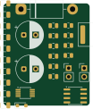
About the LTC1871 Based Boost Controller PCB
LTC1871 Based Boost Controller is an open source PCB design by fortuneolose, published on GitHub. It is a 2-layer board measuring 25.5 × 30.3 mm, with 29 components from 19 distinct parts.
Other key parts include the LTC1871EMS-7-PBF. By type, the board carries 17 capacitors, 4 resistors, 2 diodes, 1 IC, 1 transistor and 1 connector.
It belongs with the power & battery and robotics & motion designs in this gallery.
From the project
EE499 Final Year Project — LTC1871 DC-DC Boost Converter (LTSpice simulation, MATLAB analysis, report iterations)
Design, simulate, build and test a buck/boost DC-DC converter intended for use in robotics and autonomous systems such as factory automation, surveillance platforms, delivery robots, drones and e-mobility applications.
DC-DC converters supply the various voltage rails required by different sub-systems in robotic platforms. This project investigates the key design principles of a switched-mode buck/boost converter, with emphasis on:
Main components on the LTC1871 Based Boost Controller
LTC1871 Based Boost Controller bill of materials (BOM)
29 components, 19 distinct parts — part numbers from the project's BOM.
| Qty | Part | Footprint | Refs |
|---|---|---|---|
| 1 | LTC1871EMS-7-PBF | MSOP-10_3x3mm_P0.5mm | U1 |
| 1 | SI4894BDY IRF7811 | SOIC-8_3.9x4.9mm_P1.27mm | Q1 |
| 1 | J2_OUT | PinHeader_1x02_P2.54mm_Vertical | J2 |
| 1 | 100µ | CP_Radial_D8.0mm_P3.50mm | Cin1 |
| 1 | J_VIN_OUT | PinHeader_1x02_P2.54mm_Vertical | J_VIN1 |
| 1 | MBR735 | D_DO-201AD_P15.24mm_Horizontal | D1 |
| 1 | SS14 1N4148 | D_SOD-323_HandSoldering | D2 |
| 1 | 10µ | L_Coilcraft_XAL6060-XXX | L1 |
| 1 | 10n | C_0805_2012Metric | C1 |
| 10 | 22µ | C_1206_3216Metric | C1a1, C1a2, C1a3, C1a4, C1a5, C1a6, C1a7, C1a8 +2 |
| 2 | 10µ | C_0805_2012Metric | C1b1, C1b2 |
| 1 | 6.8N 6.8n | C_0805_2012Metric | C2 |
| 1 | 100P 100p | C_0805_2012Metric | C3 |
| 1 | 4.7µ | C_0805_2012Metric | C4 |
| 1 | 100µ | CP_Radial_D8.0mm_P3.50mm | C5 |
| 1 | 68.1K 68.1k | R_0805_2012Metric | R1 |
| 1 | 56K 56k | R_0805_2012Metric | R2 |
| 1 | 499K 499k | R_0805_2012Metric | R3 |
| 1 | 8.66K 8.66k | R_0805_2012Metric | R4 |
LTC1871 Based Boost Controller design files
The KiCad project lives in the fortuneolose/EE499-FYP repository on GitHub; these links point at the commit this page was built from.
- LayoutKiCAD PCB Design/LTC1871_Based_Boost_Controller/LTC1871_Based_Boost_Controller.kicad_pcb
- SchematicKiCAD PCB Design/LTC1871_Based_Boost_Controller/LTC1871_Based_Boost_Controller.kicad_sch
- BOMKiCAD PCB Design/LTC1871 KiCAD PCB Revision/jlcpcb/production_files/BOM-LTC1871_Based_Boost_Controller_V2 - Copy.csv
LTC1871 Based Boost Controller: common questions
How big is the LTC1871 Based Boost Controller PCB?
The LTC1871 Based Boost Controller measures 25.5 × 30.3 mm, has 2 copper layers and is 1.6 mm thick.
How many components are on the LTC1871 Based Boost Controller?
29 components, from 19 distinct parts, with part numbers taken from the project's own BOM. The full bill of materials is listed on this page.
Where can I download the LTC1871 Based Boost Controller design files?
From the fortuneolose/EE499-FYP repository on GitHub, which has the KiCad layout, the schematic and the BOM; the links under Design files point to each one.
Can I use the LTC1871 Based Boost Controller design in my own project?
The repository has no license, so all rights stay with fortuneolose. Use it as a reference, and ask the author before reusing the design.
More boards in EE499-FYP
Similar boards

EinkPDA screen
TalismanDesign
95 × 54 mm27 parts2LApache-2.02.0k
Stack chan
stack-chan
50 × 50 mm33 parts2LApache-2.01.7k
Display Carrier
AxxAxx
35.6 × 58.2 mm5 parts2LGPL-3.01.7k
ProgrammingAdapter
stuartpittaway
10.5 × 83 mm3 parts2LCC-BY-NC-4.01.1k
TemperaturePCB PANEL
116 × 75.5 mm178 parts2LCC-BY-NC-4.01.1k
Module 16S PassiveBalanceAddOn
61 × 74 mm86 parts2LCC-BY-NC-4.01.1k