
UPLC-Digital

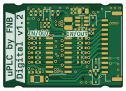
About the UPLC-Digital PCB
UPLC-Digital is an open source ESP32 PCB design by fredriknk, published on GitHub under the MIT license. It is a 4-layer board measuring 31.4 × 22 mm, with 41 components from 17 distinct parts.
Its main chip is the ESP32-C3-WROOM-02-N4, from the ESP32 family. Other key parts include the AP63201WU-7 and TBD62003AFWG. By type, the board carries 12 jumpers, 10 resistors, 9 capacitors, 4 diodes, 3 ICs and 1 crystal.
Main components on the UPLC-Digital
UPLC-Digital bill of materials (BOM)
41 components, 17 distinct parts — part numbers from the project's BOM.
| Qty | Part | Footprint | Refs |
|---|---|---|---|
| 1 | AP63201WU-7 AP63201WU | TSOT-23-6 | U1 |
| 1 | TBD62003AFWG | SOIC-16_3.9x9.9mm_P1.27mm | U2 |
| 1 | ESP32-C3-WROOM-02-N4 ESP32-C3-WROOM-02 | ESP32-C3-WROOM-02 | U3 |
| 1 | Q13FC13500004 32.768khz 3215 12.5pf | Crystal_SMD_3215-2Pin_3.2x1.5mm | Y1 |
| 1 | SM12B-GHS-TB(LF)(SN) | JST_GH_SM12B-GHS-TB_1x12-1MP_P1.25mm_Horizontal | J2 |
| 12 | RTT02000JTH 0R | SolderJumper-3_P1.3mm_BridgedSMD12_0402 | JP1, JP2, JP3, JP4, JP5, JP6, JP7, JP8 +4 |
| 4 | 1N5819WS | D_SOD-323 | D1, D2, D3, D4 |
| 1 | LQM2HPN4R7MG0L 4.7uH | L_1008_2520Metric | L1 |
| 2 | 0402CG200J500NT 20pf | C_0402_1005Metric | C1, C4 |
| 3 | GRM155R71H104KE14D 0.1uF | C_0402_1005Metric | C2, C3, C9 |
| 1 | GRM21BR6YA106KE43L 10uF | C_0805_2012Metric | C5 |
| 3 | GRM155R60J226ME11D 22uf | C_0402_1005Metric | C8, C11, C12 |
| 6 | 0402WGF1002TCE 10K | R_0402_1005Metric | R1, R2, R3, R4, R5, R6 |
| 1 | RTT023093FTH 309k | R_0402_1005Metric | R7 |
| 1 | 0402WGF1000TCE 100R | R_0402_1005Metric | R13 |
| 1 | 0402WGF1823TCE 182k | R_0402_1005Metric | R14 |
| 1 | RC0402FR-0762KL 62k | R_0402_1005Metric | R15 |
UPLC-Digital design files
The KiCad project lives in the fredriknk/uPLC-Digital repository on GitHub; these links point at the commit this page was built from.
UPLC-Digital: common questions
What microcontroller does the UPLC-Digital use?
The UPLC-Digital is built around the ESP32-C3-WROOM-02-N4, from the ESP32 family.
How big is the UPLC-Digital PCB?
The UPLC-Digital measures 31.4 × 22 mm, has 4 copper layers and is 1.6 mm thick.
How many components are on the UPLC-Digital?
41 components, from 17 distinct parts, with part numbers taken from the project's own BOM. The full bill of materials is listed on this page.
Where can I download the UPLC-Digital design files?
From the fredriknk/uPLC-Digital repository on GitHub, which has the KiCad layout, the schematic and the BOM; the links under Design files point to each one.
Can I use the UPLC-Digital design in my own project?
Yes, under the terms of its MIT license, which fredriknk chose for the repository.
Can I test firmware for the UPLC-Digital without the hardware?
Yes. HardLabs builds a simulation of the board from its netlist and BOM, so you can run and debug ESP32 firmware against it before you order a PCB.
Similar boards
 ESP32
OSO-BOOK-B1
joeycastillo
85 × 115 mm65 parts2LCC-BY-SA-4.08.1k ESP32
Powertrain
byrantech
64 × 45.4 mm171 parts4LMIT4.3k ESP32
Badge
atopile
56.3 × 39 mm239 parts4LMIT4.0k ESP32
Esp32 minimal
36.2 × 26.8 mm20 parts2LMIT4.0k ESP32
Controller
StuckAtPrototype
29 × 74 mm58 parts4LApache-2.03.8k ESP32
Racer
36 × 50.2 mm70 parts4LApache-2.03.8k