
Digichiver

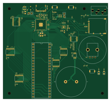
About the Digichiver PCB
Digichiver is an open source Raspberry Pi PCB design by frindaddy, published on GitHub under the MIT license. It is a 4-layer board measuring 96.9 × 88.1 mm, with 112 components from 38 distinct parts.
Its main chip is the RP2354B, from the Raspberry Pi family. Other key parts include the SN74LVC245APWR, SN74LVC8T245PWR, TLV61046A, TPSM84338 and PCM1809IRTER. By type, the board carries 54 capacitors, 36 resistors, 11 ICs, 3 connectors, 3 switches and 2 diodes.
It belongs with the audio designs in this gallery.
From the project
Archival hardware/firmware for the MM54104 Digitalker chip
The doc describes the digichicver circuit schematic (and PCB layout, when needed).
This sheet show the block diagram for the Digichiver board. The sheet is broken into 4 sections, the USB-C power/data connector, the Control block, the Digitalker block, the Audio block, and the Power block.
The USB-C connector is setup for a USB 2.0 full-speed connection, as that is the max capability of the RP2354B. Two $5.1k\Omega$ resistors tie CC1 and CC2 to ground to specify that this board is a power sink, per the USB specification. This advertises that this board can consume a maximum of 2.5W…
Main components on the Digichiver
Digichiver bill of materials (BOM)
112 components, 38 distinct parts.
| Qty | Part | Footprint | Refs |
|---|---|---|---|
| 1 | RP2354B | QFN-80-1EP_10x10mm_P0.4mm_EP3.4x3.4mm | U1 |
| 2 | SN74LVC245APWR SN74LVC245A | TSSOP-20_4.4x6.5mm_P0.65mm | U2, U3 |
| 3 | SN74LVC8T245PWR SN74LVC8T245 | TSSOP-24_4.4x7.8mm_P0.65mm | U4, U5, U6 |
| 1 | TLV61046A | SOT-23-6 | U7 |
| 1 | TPSM84338 | CONV_TPSM84338RCJR | U8 |
| 1 | PCM1809IRTER PCM1809 | PCM1820IRTER | U9 |
| 1 | TLV9004IPWR | TSSOP-14_4.4x5mm_P0.65mm | U10 |
| 1 | PAM8302AASCR | MSOP-8_3x3mm_P0.65mm | U11 |
| 1 | ABM8-272-T3 | Crystal_SMD_Abracon_ABM8G-4Pin_3.2x2.5mm | X2 |
| 1 | DM3AT-SF-PEJM5 | microSD_HC_Hirose_DM3AT-SF-PEJM5 | J1 |
| 1 | USB4105-GF-A | USB_C_Receptacle_GCT_USB4105-xx-A_16P_TopMnt_Horizontal | J2 |
| 1 | SJ1-3535NG | Jack_3.5mm_CUI_SJ1-3535NG_Horizontal | J5 |
| 3 | TS-1088-AR02016 | SW_SPST_TS-1088-xR020 | SW1, SW2, SW3 |
| 1 | KT-0805G | LED_0805_2012Metric | D1 |
| 1 | KT-0805Y | LED_0805_2012Metric | D2 |
| 1 | AOTA-B201610S3R3-101-T 3.3uH | L_0805_2012Metric | L1 |
| 1 | VLCF4020T-150MR68 15uH | IND_VLCF4020T-150MR68 | L2 |
| 27 | CL05B104KB54PNC 100nF | C_0402_1005Metric | C1, C2, C3, C4, C5, C6, C7, C8 +19 |
| 2 | 0402CG150J500NT 15pF | C_0402_1005Metric | C10, C11 |
| 4 | CL05A475MP5NRNC 4.7uF | C_0402_1005Metric | C12, C13, C14, C15 |
Show 18 more
| Qty | Part | Footprint | Refs |
|---|---|---|---|
| 5 | CL10A106MA8NRNC 10uF | C_0603_1608Metric | C31, C37, C38, C39, C48 |
| 2 | CL10A226MQ8NRNC 22uF | C_0603_1608Metric | C32, C35 |
| 11 | CL05A105KA5NQNC 1uF | C_0402_1005Metric | C33, C36, C40, C41, C49, C50, C51, C52 +3 |
| 1 | CL21A475KAQNNNE 4.7uF | C_0805_2012Metric | C34 |
| 2 | CL05B103KB5NNNC 10nF | C_0402_1005Metric | C43, C44 |
| 12 | 0402WGF1002TCE 10k | R_0402_1005Metric | R1, R2, R3, R4, R5, R12, R18, R28 +4 |
| 5 | 0402WGF1001TCE 1k | R_0402_1005Metric | R6, R7, R10, R11, R13 |
| 2 | 0603WAF270JT5E 27 | R_0603_1608Metric | R8, R9 |
| 1 | RC0402FR-07732KL 732k | R_0402_1005Metric | R14 |
| 1 | 0402WGF1802TCE 18K | R_0402_1005Metric | R15 |
| 1 | RC0402FR-0771K5L 71.5k | R_0402_1005Metric | R16 |
| 1 | RC0402FR-0745K3L 45.3k | R_0402_1005Metric | R17 |
| 2 | 0402WGF5101TCE 5.1k | R_0402_1005Metric | R19, R20 |
| 4 | 0402WGF1003TCE 100k | R_0402_1005Metric | R21, R22, R23, R36 |
| 2 | 0402WGF2201TCE 2.2k | R_0402_1005Metric | R24, R25 |
| 2 | 0402WGF8201TCE 8.2k | R_0402_1005Metric | R26, R27 |
| 1 | 0402WGF1500TCE 150 | R_0402_1005Metric | R33 |
| 2 | 0402WGF1000TCE 100 | R_0402_1005Metric | R34, R35 |
Digichiver design files
The KiCad project lives in the frindaddy/digichiver repository on GitHub; these links point at the commit this page was built from.
- LayoutHardware/Digichiver.kicad_pcb
- SchematicHardware/Digichiver.kicad_sch
Digichiver: common questions
What microcontroller does the Digichiver use?
The Digichiver is built around the RP2354B, from the Raspberry Pi family.
How big is the Digichiver PCB?
The Digichiver measures 96.9 × 88.1 mm, has 4 copper layers and is 1.6 mm thick.
How many components are on the Digichiver?
112 components, from 38 distinct parts. The full bill of materials is listed on this page.
Where can I download the Digichiver design files?
From the frindaddy/digichiver repository on GitHub, which has the KiCad layout and the schematic; the links under Design files point to each one.
Can I use the Digichiver design in my own project?
Yes, under the terms of its MIT license, which frindaddy chose for the repository.
Can I test firmware for the Digichiver without the hardware?
Yes. HardLabs builds a simulation of the board from its netlist and BOM, so you can run and debug Raspberry Pi firmware against it before you order a PCB.
Similar boards
 Raspberry Pi
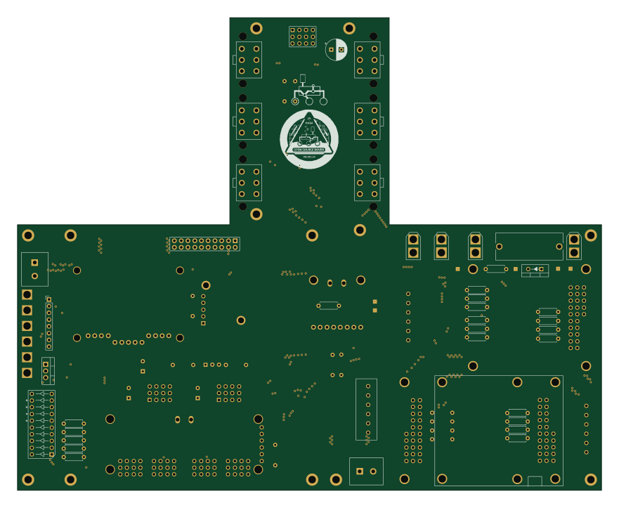
Open source rover
nasa-jpl
220 × 178 mm144 parts2LApache-2.09.7k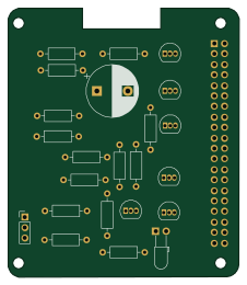 Raspberry Pi
Iot
dotnet
56 × 65 mm24 parts2LMIT2.4k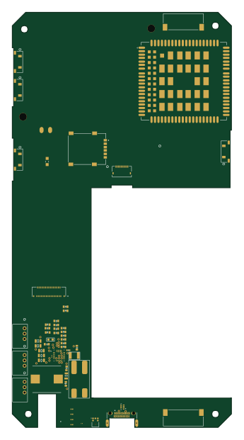 Raspberry Pi
SPIRIT
SPIRIT-org
82 × 155 mm130 parts6LCERN-OHL-S-2.01.3k Raspberry Pi
CM5RevEng
schlae
55 × 40 mm417 parts10LNo license1.0k Raspberry Pi
Haxo hw
cardonabits
102.4 × 211.3 mm38 parts2LCustom license672 Raspberry Pi
Phased
Neumi
75 × 100 mm71 parts2LNo license507