
Stepper-Motor-Controller

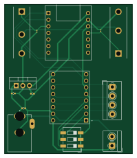
About the Stepper-Motor-Controller PCB
Stepper-Motor-Controller is an open source RP2040/RP2350 PCB design by Gautham-8066, published on GitHub. It is a 2-layer board measuring 49.1 × 57.4 mm, with 14 components from 12 distinct parts.
Its main chip is the MOUDLE-SEEEDUINO-XIAO, from the RP2040/RP2350 family. Other key parts include the DRV8825_STEPPER_MOTOR_DRIVER_CARRIER and LM7805_TO220. By type, the board carries 3 ICs, 3 connectors, 3 switches, 3 capacitors and 2 resistors.
It belongs with the robotics & motion designs in this gallery.
From the project
This board allows users to drive a stepper motor. This board has a xiao microcontroller,DRV8825 driver,limit switch detection for homing and end-stop functionality. It is ideal for CNC machines, 3D printers, robotics, and automation projects.
Don't mind the limit switch placement on the PCB, I know it can't be used if its placed there, but I don't know another way to show it in 3D view instead of placing on the PCB. I think you may Understand :)
Main components on the Stepper-Motor-Controller
Stepper-Motor-Controller bill of materials (BOM)
14 components, 12 distinct parts.
| Qty | Part | Footprint | Refs |
|---|---|---|---|
| 1 | MOUDLE-SEEEDUINO-XIAO | MOUDLE14P-2.54-21X17.8MM | U1 |
| 1 | DRV8825_STEPPER_MOTOR_DRIVER_CARRIER | IC_DRV8825_STEPPER_MOTOR_DRIVER_CARRIER | U2 |
| 1 | LM7805_TO220 | TO-220-3_Vertical | U4 |
| 1 | Screw_Terminal_01x02 | TerminalBlock_4Ucon_1x02_P3.50mm_Horizontal | J1 |
| 1 | Screw_Terminal_01x04 | TerminalBlock_4Ucon_1x04_P3.50mm_Horizontal | J2 |
| 1 | DCJ200-10-A-XX-K_REVA | GCT_DCJ200-10-A-XX-K_REVA | J3 |
| 2 | MS0850502F030P1A | SW_MS0850502F030P1A | S1, S2 |
| 1 | SW_DIP_x03 | SW_DIP_SPSTx03_Slide_6.7x9.18mm_W6.73mm_P2.54mm_LowProfile_JPin | SW1 |
| 1 | 100u | C_0402_1005Metric_Pad0.74x0.62mm_HandSolder | C1 |
| 1 | 0.22u | C_0402_1005Metric_Pad0.74x0.62mm_HandSolder | C2 |
| 1 | 0.1u | C_0402_1005Metric_Pad0.74x0.62mm_HandSolder | C3 |
| 2 | 10k | R_0201_0603Metric | R1, R2 |
Stepper-Motor-Controller design files
The KiCad project lives in the Gautham-8066/Stepper-Motor-Controller-PCB repository on GitHub; these links point at the commit this page was built from.
Stepper-Motor-Controller: common questions
What microcontroller does the Stepper-Motor-Controller use?
The Stepper-Motor-Controller is built around the MOUDLE-SEEEDUINO-XIAO, from the RP2040/RP2350 family.
How big is the Stepper-Motor-Controller PCB?
The Stepper-Motor-Controller measures 49.1 × 57.4 mm, has 2 copper layers and is 1.6 mm thick.
How many components are on the Stepper-Motor-Controller?
14 components, from 12 distinct parts. The full bill of materials is listed on this page.
Where can I download the Stepper-Motor-Controller design files?
From the Gautham-8066/Stepper-Motor-Controller-PCB repository on GitHub, which has the KiCad layout and the schematic; the links under Design files point to each one.
Can I use the Stepper-Motor-Controller design in my own project?
The repository has no license, so all rights stay with Gautham-8066. Use it as a reference, and ask the author before reusing the design.
Can I test firmware for the Stepper-Motor-Controller without the hardware?
Yes. HardLabs builds a simulation of the board from its netlist and BOM, so you can run and debug RP2040/RP2350 firmware against it before you order a PCB.
Similar boards
 RP2040/RP2350
Open Book Abridged Edition
joeycastillo
85 × 115 mm29 parts2LCC-BY-SA-4.08.1k RP2040/RP2350
Corne
foostan
277.2 × 107.5 mm164 parts2LCC-BY-4.07.7k RP2040/RP2350
Corne
277.2 × 107.5 mm164 parts2LCC-BY-4.07.7k RP2040/RP2350
LogicAnalyzer
gusmanb
57 × 55.2 mm6 parts2LGPL-3.05.0k RP2040/RP2350
Jitx design
55.5 × 65 mm26 parts4LGPL-3.05.0k RP2040/RP2350
Pro V2
kata0510
290.1 × 130 mm270 parts2LMIT2.3k