
GG-Battle robot

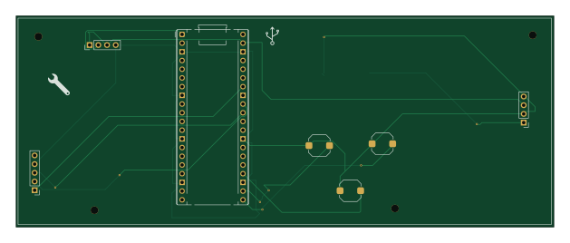
About the GG-Battle robot PCB
GG-Battle robot is an open source Raspberry Pi PCB design by gethin101, published on GitHub. It is a 2-layer board measuring 156.9 × 61.5 mm, with 9 components from 9 distinct parts.
Its main chip is the RaspberryPi_Pico_W, from the Raspberry Pi family. By type, the board carries 3 switches, 2 connectors and 1 module.
It belongs with the robotics & motion, audio and displays & leds designs in this gallery.
From the project
Custom robot wars inspired GG Battle Robot designed during Hackclub’s blueprint YSWS program
It runs on a Raspberry pi pico H, TT motors, L298N motor drivers, and a servo motor. It is controlled by a 433mhz radio frequency remote, another Raspberry pi pico H, a joystick module and extra control buttons. The 2 main axe weapons and chassis will be 3d printed in PLA.
I am also using a 1.8" SPI LCD Display for the robot to display information on the front of the robot and SK6812 MINI-E RGB leds for the back of the robot. These will both be powered by being plugged into the breadboard in the robot using the pins and jumper wires.
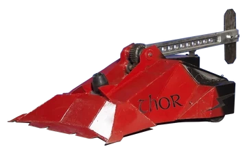
Main components on the GG-Battle robot
GG-Battle robot bill of materials (BOM)
9 components, 9 distinct parts — part numbers from the project's BOM.
| Qty | Part | Footprint | Refs |
|---|---|---|---|
| 1 | RaspberryPi_Pico_W | RaspberryPi_Pico_Common_THT | A1 |
| 1 | RF_TX | PinHeader_1x04_P2.54mm_Vertical | J1 |
| 1 | JOY | PinHeader_1x05_P2.54mm_Vertical | J2 |
| 1 | BAT+ | SolderWirePad_1x01_SMD_5x10mm | J_BAT+1 |
| 1 | BAT- | SolderWirePad_1x01_SMD_5x10mm | J_BAT-1 |
| 1 | MT3608 | PinHeader_1x04_P2.54mm_Vertical | J_BOOST1 |
| 1 | BTN_AXE_DOWN | SW_Push_1TS009xxxx-xxxx-xxxx_6x6x5mm | SW1 |
| 1 | BTN_AXE_UP | SW_Push_1TS009xxxx-xxxx-xxxx_6x6x5mm | SW2 |
| 1 | BTN_SFX | SW_Push_1TS009xxxx-xxxx-xxxx_6x6x5mm | SW3 |
GG-Battle robot design files
The KiCad project lives in the gethin101/GG-Battle-robot repository on GitHub; these links point at the commit this page was built from.
GG-Battle robot: common questions
What microcontroller does the GG-Battle robot use?
The GG-Battle robot is built around the RaspberryPi_Pico_W, from the Raspberry Pi family.
How big is the GG-Battle robot PCB?
The GG-Battle robot measures 156.9 × 61.5 mm, has 2 copper layers and is 1.6 mm thick.
How many components are on the GG-Battle robot?
9 components, from 9 distinct parts, with part numbers taken from the project's own BOM. The full bill of materials is listed on this page.
Where can I download the GG-Battle robot design files?
From the gethin101/GG-Battle-robot repository on GitHub, which has the KiCad layout, the schematic and the BOM; the links under Design files point to each one.
Can I use the GG-Battle robot design in my own project?
The repository has no license, so all rights stay with gethin101. Use it as a reference, and ask the author before reusing the design.
Can I test firmware for the GG-Battle robot without the hardware?
Yes. HardLabs builds a simulation of the board from its netlist and BOM, so you can run and debug Raspberry Pi firmware against it before you order a PCB.
Similar boards
 Raspberry Pi
Haxo hw
cardonabits
102.4 × 211.3 mm38 parts2LCustom license672 Raspberry Pi
PowerBook
BlueSCSI
74.5 × 56.3 mm78 parts2LGPL-3.0449 Raspberry Pi
Desktop 50 Pin TopConn
89.2 × 82.6 mm103 parts2LGPL-3.0449 Raspberry Pi
BitDogLab 5.4
BitDogLab
87.9 × 123.9 mm56 parts2LCERN-OHL-S-2.0201 Raspberry Pi
BitDogLab Main SMD version
87.9 × 98.7 mm124 parts2LCERN-OHL-S-2.0201 Raspberry Pi
Zynthian mini v2 20 buttons short
zynthian
163 × 120 mm87 parts2LNo license154