
T12 Control

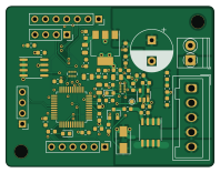
About the T12 Control PCB
T12 Control is an open source STM32 PCB design by ghent360, published on GitHub under the Custom license license. It is a 4-layer board measuring 49.5 × 38.2 mm, with 45 components from 30 distinct parts.
Its main chip is the STM32F407VET6, from the STM32 family. Other key parts include the 74LVC125, 24LC64T-I/SN and AMS1117-3.3. By type, the board carries 19 capacitors, 13 resistors, 4 ICs, 4 inductors, 3 diodes and 2 transistors.
It belongs with the robotics & motion designs in this gallery.
From the project
32-bit 3D Printer controller board using STM32F407 and replaceable TMC2660/2209 stepper drivers.
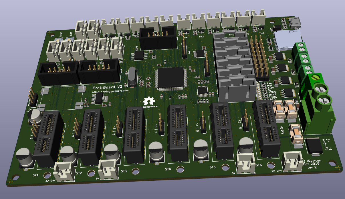
PrntrBoard V2 ====================== PrntrBoard V2 is the next iteration of my 3D printer controller design. The V1 was very good, except it had one major drawback - the stepper drivers were soldered on the board which would make the design expensive. This V2 design has 6 replaceable motor drivers. While traditional RAMPS based boards use pin headers to house the driver boards, I'm using PCIe 1x slots. This design has several advantages: + the driver PCB layout can be more flexible as there are fewer constraints on the driver board dimensions + drivers are placed vertically on the board which…
Main components on the T12 Control
T12 Control bill of materials (BOM)
45 components, 30 distinct parts — part numbers from the project's BOM.
| Qty | Part | Footprint | Refs |
|---|---|---|---|
| 1 | 74LVC125 SPX2954M3-3.3_SOT223 | SOT-223-3_TabPin2 | U1 |
| 1 | STM32F407VET6 24LC32 | SOIC-8_3.9x4.9mm_P1.27mm | U2 |
| 1 | 24LC64T-I/SN SGM8551XN | SOT-23-5 | U3 |
| 1 | AMS1117-3.3 STM32F103CBTx | LQFP-48_7x7mm_P0.5mm | U4 |
| 1 | NCE40P40K TPC8107 | SO-8_3.9x4.9mm_P1.27mm | Q1 |
| 1 | BC817 | SOT-23 | Q2 |
| 1 | B5819W RS1M | D_SMA | D1 |
| 2 | KT-0603R RED | LED_0603_1608Metric | D2, D3 |
| 1 | GZ2012D601TF Ferrite_Bead | L_0805_2012Metric | FB1 |
| 3 | Ferrite_Bead | L_0805_2012Metric | FB2, FB3, FB4 |
| 9 | CC0603KRX7R9BB104 100nF | C_0603_1608Metric | C1, C4, C7, C8, C9, C11, C13, C14 +1 |
| 2 | CL10A106KP8NNNC 100nF | C_0603_1608Metric | C2, C6 |
| 1 | CL10B102KB8NNNC 100nF | C_0603_1608Metric | C3 |
| 1 | CL10A106KP8NNNC 10uF | C_0603_1608Metric | C5 |
| 2 | CC0603KRX7R9BB104 10nF | C_0603_1608Metric | C10, C18 |
| 1 | CC0603KRX7R9BB104 100uF 35V | CP_Radial_D10.0mm_P5.00mm | C12 |
| 1 | CL10A106KP8NNNC 1nF | C_0603_1608Metric | C15 |
| 1 | CL10B102KB8NNNC 470pF | C_0603_1608Metric | C16 |
| 1 | CC0603KRX7R9BB104 1uF | C_0603_1608Metric | C19 |
| 1 | 0603WAF1002T5E 2k | R_0603_1608Metric | R1 |
Show 10 more
| Qty | Part | Footprint | Refs |
|---|---|---|---|
| 2 | 0603WAF1002T5E 10k | R_0603_1608Metric | R2, R7 |
| 1 | 0603WAF1002T5E 1k | R_0603_1608Metric | R3 |
| 1 | 1k | R_0603_1608Metric | R4 |
| 1 | 0603WAF1002T5E 1k 0.1% | R_0603_1608Metric | R5 |
| 1 | 0603WAF1002T5E 249k 0.1% | R_0603_1608Metric | R6 |
| 1 | 0603WAF1001T5E 470 | R_0603_1608Metric | R8 |
| 1 | 0603WAF1501T5E 1k | R_0603_1608Metric | R9 |
| 1 | 0603WAF220JT5E 2.2 | R_0603_1608Metric | R10 |
| 1 | 0603WAF220JT5E 4.7k 1% | R_0603_1608Metric | R11 |
| 2 | 4D03WGJ0471T5E 4x4.7k | R_Array_Concave_4x0402 | RN1, RN2 |
T12 Control design files
The KiCad project lives in the ghent360/PrntrBoardV2 repository on GitHub; these links point at the commit this page was built from.
T12 Control: common questions
What microcontroller does the T12 Control use?
The T12 Control is built around the STM32F407VET6, from the STM32 family.
How big is the T12 Control PCB?
The T12 Control measures 49.5 × 38.2 mm, has 4 copper layers and is 1.59 mm thick.
How many components are on the T12 Control?
45 components, from 30 distinct parts, with part numbers taken from the project's own BOM. The full bill of materials is listed on this page.
Where can I download the T12 Control design files?
From the ghent360/PrntrBoardV2 repository on GitHub, which has the KiCad layout, the schematic and the BOM; the links under Design files point to each one.
Can I use the T12 Control design in my own project?
It is published under Custom license, which limits how it may be reused; read the license before building on it.
Can I test firmware for the T12 Control without the hardware?
Yes. HardLabs builds a simulation of the board from its netlist and BOM, so you can run and debug STM32 firmware against it before you order a PCB.
More boards in PrntrBoardV2
 STM32
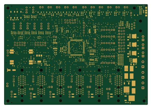
STM32PrntrBoardV2
148.7 × 104.3 mm272 parts2LCustom license45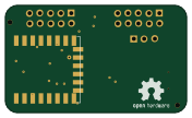 ESP8266
WiFi-Addon
44 × 26 mm28 parts2LCustom license45 STM32
STM32TMC2130 Driver
36.7 × 39.4 mm24 parts2LCustom license45 STM32
STM32TMC2660 Driver
36.7 × 39.4 mm23 parts4LCustom license45 STM32
STM32TMC2209 Driver
36.7 × 39.4 mm22 parts2LCustom license45 STM32
STM32DRV-StepStick
36.7 × 39.4 mm14 parts2LCustom license45
MP-Power
17 × 15.7 mm12 parts2LCustom license45
XL-Power
27 × 22 mm6 parts2LCustom license45
LcdFlip
45.5 × 18 mm4 parts2LCustom license45
Similar boards
 STM32
STM32LumenPnP Motherboard
opulo-inc
149 × 95 mm296 parts4LCC-BY-SA-4.03.7k STM32
STM32AxxSolder
AxxAxx
39 × 82.5 mm122 parts2LGPL-3.01.7k STM32
STM32AIOC
skuep
21 × 31.5 mm47 parts2LMIT1.4k STM32
STM32Ferris
pierrechevalier83
208.8 × 86.8 mm102 parts2LSHL-2.11.3k STM32
STM32Module 16S
stuartpittaway
71.1 × 89.6 mm113 parts4LCC-BY-NC-4.01.1k STM32
STM32Djinn
tzarc
192.3 × 150.5 mm216 parts2LCERN-OHL-S-2.0988