
18 open source boards using the STM32F407VET6
Real designs built with the STM32F407VET6, from public GitHub projects: a quick way to see how others power, decouple and connect it. Each board comes with its KiCad files, full parts list and a render — and you can simulate its firmware on HardLabs.
 STM32
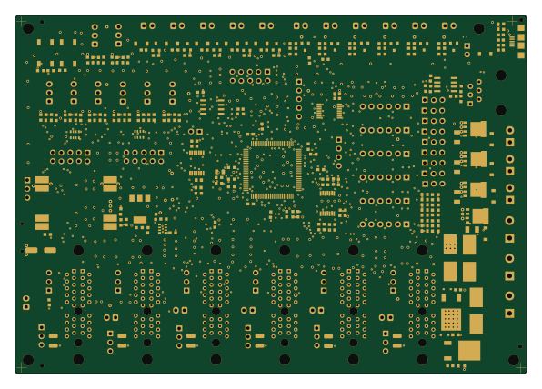
PrntrBoardV2
ghent360
148.7 × 104.3 mm272 parts2LCustom license45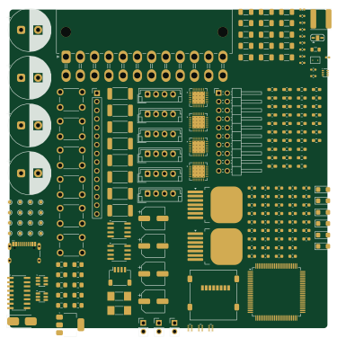 STM32
Harpia
todio1155
93.6 × 93.8 mm182 parts6LCERN-OHL-S-2.01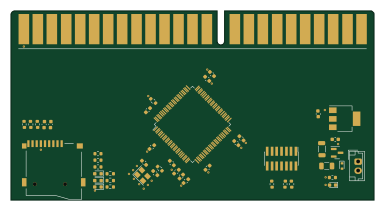 STM32
Sm2m sdmmc
artemkorobko
96 × 50 mm47 parts4LNo license1 STM32
OpenPNP mobo
jaytektas
180 × 140 mm382 parts4LNo license0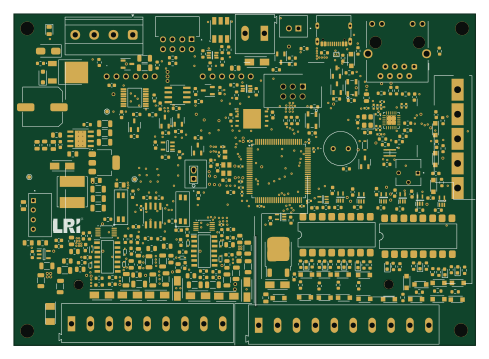 STM32
AEM-60DC8 V1.2
akhemka-cmd
122 × 87.6 mm350 parts2LNo license0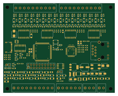 STM32
Placed
danhmanu
100 × 80 mm310 parts2LNo license0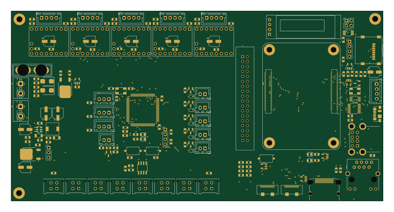 STM32
XYmatics-E64
XyrusB2010
191.3 × 97.8 mm277 parts2LNo license0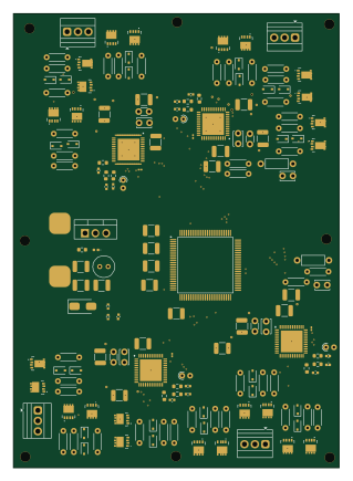 STM32
4in1-ESC-STM32F407-DRV8323
alexWandugu
77.8 × 108.6 mm172 parts4LMIT0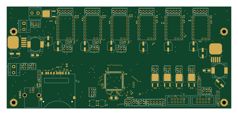 STM32
Super3DMaker
ChladpavPy
189.6 × 85.9 mm142 parts4LNo license0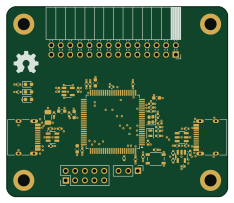 STM32
MiniMPE
adrienles
58.5 × 50.3 mm55 parts4LNo license0- schematic only · 1 partsSTM32
WiT
notazizelse
1 partsNo license0 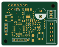 STM32
T12 Control
49.5 × 38.2 mm45 parts4LCustom license45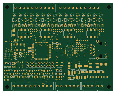 STM32
PLC STM32 Modbus
100 × 80 mm310 parts2LNo license0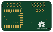 ESP8266
WiFi-Addon
44 × 26 mm28 parts2LCustom license45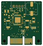 STM32
TMC2130 Driver
36.7 × 39.4 mm24 parts2LCustom license45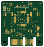 STM32
TMC2660 Driver
36.7 × 39.4 mm23 parts4LCustom license45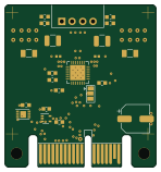 STM32
TMC2209 Driver
36.7 × 39.4 mm22 parts2LCustom license45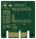 STM32
DRV-StepStick
36.7 × 39.4 mm14 parts2LCustom license45
How designs wire the STM32F407VET6
Read from the KiCad layouts of 10 open source designs, one per repository: what each pin of the STM32F407VET6 connects to, and the resistors, capacitors and other passives placed on it.
- The VDD pins have a decoupling capacitor on 9 of 10 designs, most often 100 nF (then 10 µF).
- The VCAP_1 pin has a capacitor to GND on 9 of 10 designs, most often 2.2 µF (then 10 µF).
- The VCAP_2 pin has a capacitor to GND on 9 of 10 designs, most often 2.2 µF (then 10 µF).
- The VBAT pin has a decoupling capacitor on 8 of 10 designs, most often 100 nF (then 10 µF).
| Pin | Connected to | Parts on the pin |
|---|---|---|
| VBATpin 6 | Connected to: 3.3V 70% · a signal 20% |
|
| PC13pin 7 | Connected to: Not connected 80% · a signal 20% | — |
| PC14pin 8 | Connected to: Not connected 60% · a signal 40% | — |
| VSSpin 10, 27, 74, 99 | Connected to: GND 100% | — |
| VDDpin 11, 19, 28, 50, 75, 100 | Connected to: 3.3V 90% |
|
| PH0pin 12 | Connected to: Signal 90% |
|
| PH1pin 13 | Connected to: Signal 80% · not connected 20% |
|
| NRSTpin 14 | Connected to: A connector 70% |
|
| PC0pin 15 | Connected to: A connector 30% · not connected 20% |
|
| PC1pin 16 | Connected to: A connector 30% · not connected 20% |
|
| PC2pin 17 | Connected to: A connector 30% · not connected 20% |
|
| VSSApin 20 | Connected to: GND 100% | — |
| VREF+pin 21 | Connected to: 3.3V 80% |
|
| VDDApin 22 | Connected to: 3.3V 80% · a signal 20% |
|
| PA0pin 23 | Connected to: A connector 20% · not connected 20% |
|
| PA1pin 24 | Connected to: A connector 20% · not connected 20% |
|
| PA2pin 25 | Connected to: A connector 20% |
|
| PA3pin 26 | Connected to: A connector 20% · not connected 20% |
|
| PA4pin 29 | Connected to: A connector 20% · not connected 30% |
|
| PA5pin 30 | Connected to: A connector 20% · not connected 30% |
|
| PA6pin 31 | Connected to: A connector 20% · not connected 30% |
|
| PA7pin 32 | Connected to: A connector 20% · not connected 30% |
|
| PC4pin 33 | Connected to: Signal 70% · not connected 30% |
|
| PC5pin 34 | Connected to: Signal 80% · not connected 20% |
|
| PB0pin 35 | Connected to: Signal 60% · not connected 40% |
|
| PB1pin 36 | Connected to: Signal 60% · not connected 40% |
|
| PB2pin 37 | Connected to: Signal 60% · not connected 40% |
|
| PE7pin 38 | Connected to: Not connected 60% · a signal 40% |
|
| PE8pin 39 | Connected to: Signal 70% · not connected 30% |
|
| PE9pin 40 | Connected to: Signal 60% · not connected 40% |
|
| PE11pin 42 | Connected to: Signal 60% · not connected 40% |
|
| PE12pin 43 | Connected to: Signal 70% · not connected 30% |
|
| PE13pin 44 | Connected to: Signal 70% · not connected 30% |
|
| PE14pin 45 | Connected to: Signal 60% · not connected 40% |
|
| PE15pin 46 | Connected to: Signal 70% · not connected 30% |
|
| PB10pin 47 | Connected to: Not connected 60% · a signal 40% | — |
| VCAP_1pin 49 | Connected to: Signal 90% |
|
| PB12pin 51 | Connected to: Signal 80% · not connected 20% |
|
| PD8pin 55 | Connected to: Not connected 60% · a signal 40% | — |
| PD9pin 56 | Connected to: Not connected 60% · a signal 40% | — |
52 more pins vary from design to design. Connections count pins, parts count designs; values in brackets are how many parts had that value. Designs read include PrntrBoardV2 by ghent360, Sm2m sdmmc by artemkorobko, Harpia by todio1155 and MiniMPE by adrienles.
The STM32F407VET6 in open source designs
The gallery holds 18 open source boards using the STM32F407VET6 from 11 GitHub repositories; a typical one measures about 93.6 × 80 mm and carries around 99 components.
53% are two-layer designs, the rest use four layers or more, and 11% carry an open source license.
The most starred is PrntrBoardV2 by ghent360.
Parts used alongside the STM32F407VET6
What boards using the STM32F407VET6 are built for
STM32F407VET6: common questions
Where can I find a STM32F407VET6 reference design?
Each of the 18 boards on this page is a real design using the STM32F407VET6. Open one to see how it is wired up, with the full BOM, a render of the layout and links to its KiCad files.
What decoupling capacitors do designs use on the STM32F407VET6 VDD pin?
The VDD pins have a decoupling capacitor on 9 of 10 designs, most often 100 nF (then 10 µF). Counted from the KiCad layouts of 10 open source designs using the STM32F407VET6.
How is the STM32F407VET6 VCAP_1 pin connected?
The VCAP_1 pin has a capacitor to GND on 9 of 10 designs, most often 2.2 µF (then 10 µF). Counted from the KiCad layouts of 10 open source designs using the STM32F407VET6.
How is the STM32F407VET6 VCAP_2 pin connected?
The VCAP_2 pin has a capacitor to GND on 9 of 10 designs, most often 2.2 µF (then 10 µF). Counted from the KiCad layouts of 10 open source designs using the STM32F407VET6.
What parts are used alongside the STM32F407VET6?
The AMS1117-3.3, TMC2209-LA-T, TMC2209_SILENTSTEPSTICK and USBLC6-2SC6 appear in the most repositories here.
Which microcontrollers do boards using the STM32F407VET6 use?
Most are built on STM32 (17) and ESP8266 (1).
How big is a typical board using the STM32F407VET6?
The median is 93.6 × 80 mm, and 53% are two-layer designs.
What is the most popular open source board using the STM32F407VET6?
By GitHub stars, PrntrBoardV2 by ghent360, with 45 stars.
Can I simulate one of these boards using the STM32F407VET6 before building it?
Yes. HardLabs turns a board's netlist and BOM into a working simulation, so you can boot and test firmware against it with no hardware on your desk.