
BTZ-EndDevice

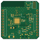
About the BTZ-EndDevice PCB
BTZ-EndDevice is an open source Nordic nRF PCB design by GoodByte-Hardware, published on GitHub under the MIT license. It is a 4-layer board measuring 35 × 35 mm, with 53 components from 38 distinct parts.
Its main chip is the NRF54L15-QFXX, from the Nordic nRF family. Other key parts include the BMI270, STS4X and LTR-329ALS-01. By type, the board carries 19 capacitors, 10 resistors, 5 connectors, 5 inductors, 4 ICs and 3 transistors.
It belongs with the iot & wireless and sensors designs in this gallery.
From the project
BTZ-EndDevice is a battery-powered sensor node designed by GoodByte to compare BLE Mesh, Thread/Matter and Zigbee on the same hardware.
BTZ-EndDevice is a battery-powered sensor node designed by GoodByte to compare BLE Mesh, Thread/Matter and Zigbee on the same hardware.
All files below are generated by KiBot in CI.
. ├─ 3D # STEP model of the board ├─ HTML # Generated web page with all outputs ├─ Images # Renders │ ├─ kibotresources # External resources for KiBot │ ├─ colors # Color theme for KiCad │ ├─ fonts # Fonts used in the project │ ├─ scripts # External scripts used with KiBot │ └─ templates # Templates for KiBot generated reports │ ├─ kibotyaml # KiBot YAML config files ├─ KiRI # KiRI (visual schematic and PCB diff…
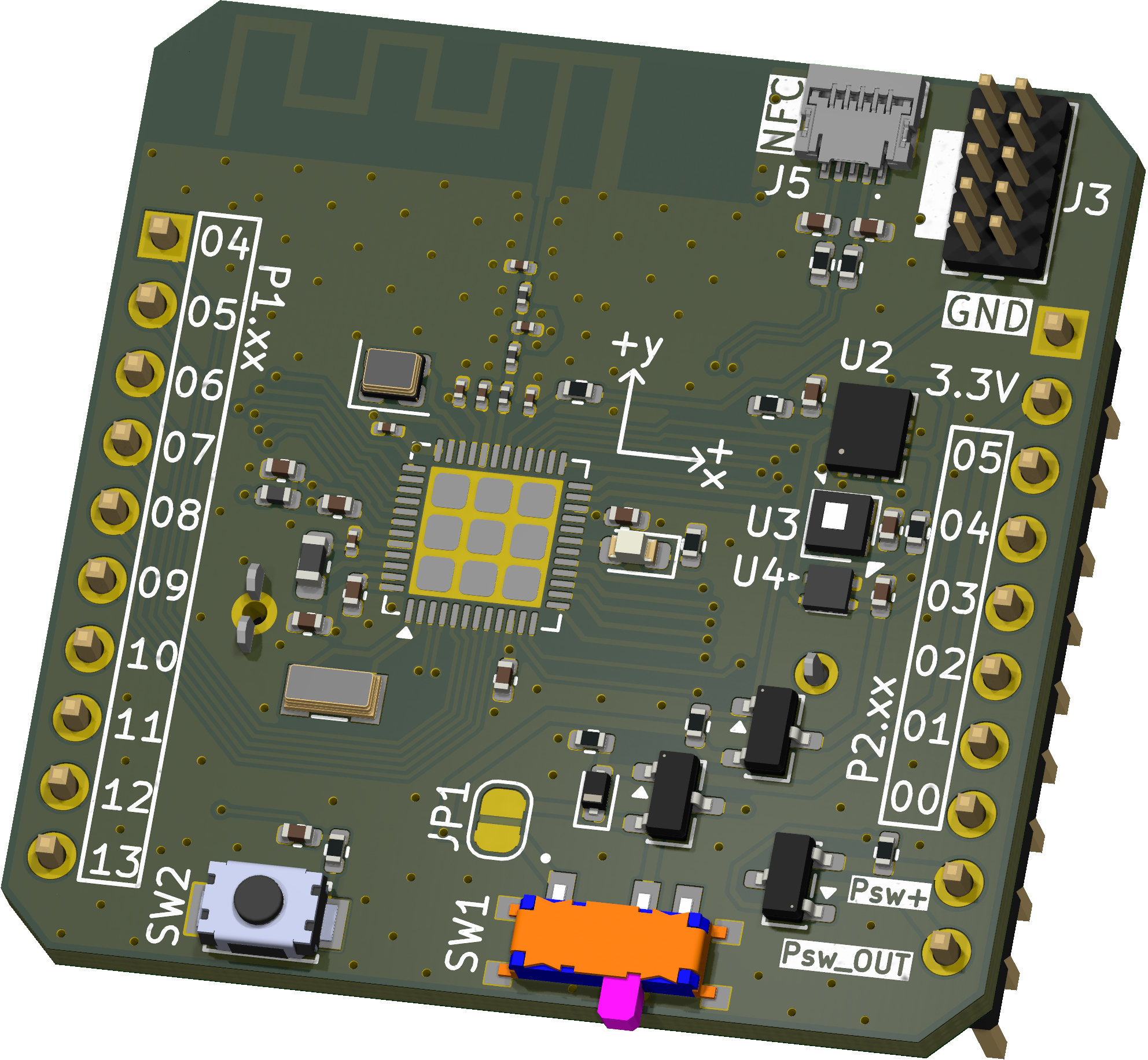
Main components on the BTZ-EndDevice
BTZ-EndDevice bill of materials (BOM)
53 components, 38 distinct parts — part numbers from the project's BOM.
| Qty | Part | Footprint | Refs |
|---|---|---|---|
| 1 | NRF54L15-QFXX nRF54L15-QFXX | QFN-48-1EP_6x6mm_P0.4mm_EP4.6x4.6mm | U1 |
| 1 | BMI270 | Bosch_LGA-14_3x2.5mm_P0.5mm | U2 |
| 1 | STS4X | STS4X | U3 |
| 1 | LTR-329ALS-01 Lite-On | Lite-On_LTR-329ALS-01 | U4 |
| 3 | AO3401A | SOT-23 | Q1, Q2, Q3 |
| 1 | 32MHZ 32MHz | Crystal_SMD_2016-4Pin_2.0x1.6mm | Y1 |
| 1 | 32.768KHZ 32.768kHz | Crystal_SMD_3215-2Pin_3.2x1.5mm | Y2 |
| 1 | A1001WR-S-2P Conn_01x02_MountingPin | 2035580207 | J1 |
| 2 | Conn_01x10_Pin | PinHeader_1x10_P2.54mm_Vertical | J2, J4 |
| 1 | A1001WR-S-2P Conn_ARM_JTAG_SWD_10 | PinHeader_2x05_P1.27mm_Vertical | J3 |
| 1 | 59453-051110ECHLF Conn_01x05_MountingPin Amphenol FCI | 59453051110ECHLF | J5 |
| 1 | BAT-HLD-001-TR CR2032 TE Connectivity | CR2032holder | BT1 |
| 1 | SW_SPDT | SSSS810701 | SW1 |
| 1 | SW_SPST | SW_TS-1088-AR02016 | SW2 |
| 1 | D_Schottky | D_SOD-523 | D1 |
| 1 | LED | LED_0603_1608Metric | D2 |
| 1 | 120R@100MHz | L_0402_1005Metric | FB1 |
| 1 | 4,7μH | L_0603_1608Metric | L1 |
| 1 | 2,7nH | L_0201_0603Metric | L2 |
| 2 | 3,5nH | L_0201_0603Metric | L3, L4 |
Show 18 more
| Qty | Part | Footprint | Refs |
|---|---|---|---|
| 1 | 10μF | C_0402_1005Metric | C1 |
| 6 | 100NF 100nF | C_0402_1005Metric | C2, C3, C5, C13, C15, C16 |
| 1 | 100NF 100nF | C_0201_0603Metric | C4 |
| 1 | 2,2nF | C_0201_0603Metric | C6 |
| 2 | 10NF 10nF | C_0402_1005Metric | C7, C18 |
| 1 | 2,2μF | C_0402_1005Metric | C8 |
| 1 | 2,2μF | C_0201_0603Metric | C9 |
| 1 | 1,5pF | C_0201_0603Metric | C10 |
| 1 | 2PF 2pF | C_0201_0603Metric | C11 |
| 1 | 0.3PF 0.3pF | C_0201_0603Metric | C12 |
| 1 | 3,9pF | C_0201_0603Metric | C14 |
| 2 | 300PF 300pF | C_0402_1005Metric | C17, C19 |
| 2 | 470K 470k | R_0402_1005Metric | R1, R7 |
| 1 | 1M | R_0402_1005Metric | R2 |
| 1 | 3,3k | R_0402_1005Metric | R3 |
| 2 | 10K 10k | R_0402_1005Metric | R4, R5 |
| 2 | 1k | R_0402_1005Metric | R6, R9 |
| 2 | 0R | R_0402_1005Metric | R8, R10 |
BTZ-EndDevice design files
The KiCad project lives in the GoodByte-Hardware/BTZ-EndDevice repository on GitHub; these links point at the commit this page was built from.
BTZ-EndDevice: common questions
What microcontroller does the BTZ-EndDevice use?
The BTZ-EndDevice is built around the NRF54L15-QFXX, from the Nordic nRF family.
How big is the BTZ-EndDevice PCB?
The BTZ-EndDevice measures 35 × 35 mm, has 4 copper layers and is 1.66 mm thick.
How many components are on the BTZ-EndDevice?
53 components, from 38 distinct parts, with part numbers taken from the project's own BOM. The full bill of materials is listed on this page.
Where can I download the BTZ-EndDevice design files?
From the GoodByte-Hardware/BTZ-EndDevice repository on GitHub, which has the KiCad layout, the schematic and the BOM; the links under Design files point to each one.
Can I use the BTZ-EndDevice design in my own project?
Yes, under the terms of its MIT license, which GoodByte-Hardware chose for the repository.
Can I test firmware for the BTZ-EndDevice without the hardware?
Yes. HardLabs builds a simulation of the board from its netlist and BOM, so you can run and debug Nordic nRF firmware against it before you order a PCB.
Similar boards
 Nordic nRF
Keyboard
byrantech
262.5 × 109.6 mm206 parts2LMIT4.3k Nordic nRF
TOTEM
GEIGEIGEIST
258.8 × 94.4 mm85 parts2LCERN-OHL-P-2.02.0k Nordic nRF
Pixl.js
solosky
40 × 23 mm45 parts4LGPL-2.01.4k Nordic nRF
Management
dennisss
101 × 31.5 mm50 parts2LApache-2.0381 Nordic nRF
Board
363 × 128 mm420 parts4LApache-2.0381 Nordic nRF
Board hl15-latest
61 × 37 mm14 parts2LApache-2.0381