
GpsLoggerLoRa

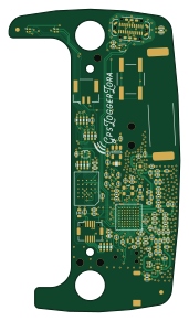
About the GpsLoggerLoRa PCB
GpsLoggerLoRa is an open source Microchip SAM PCB design by gregdavill, published on GitHub under the MIT license. It is a 4-layer board measuring 40.9 × 72.6 mm, with 110 components from 50 distinct parts.
Its main chip is the ATSAMR34J18B, from the Microchip SAM family. Other key parts include the SKY13373, MCP73832, NCP167, MT25QL256ABA8E12 and NUP2114. By type, the board carries 59 capacitors, 23 inductors, 9 resistors, 8 ICs, 3 connectors and 2 modules.
It belongs with the rf & radio designs in this gallery.
From the project
Project Stage: Firmware Devlopment v0.1a Prototyp Assembled Current Bugs: FLASH footprint wrong (fix in v0.2) Change BOM MCP73812 (CE pin) to MCP73832 (STATUS pin) Small changes to RF paths Update solderpaste apertures on X2SON parts (too much paste) Needs more test-points LED co
Project Stage: Firmware Devlopment v0.1a Prototyp Assembled Current Bugs: FLASH footprint wrong (fix in v0.2) Change BOM MCP73812 (CE pin) to MCP73832 (STATUS pin) Small changes to RF paths Update solderpaste apertures on X2SON parts (too much paste) Needs more test-points LED colours B/G swapped
A basic portable GPS logger with LoRa wireless based on Microchip ATSAMR34
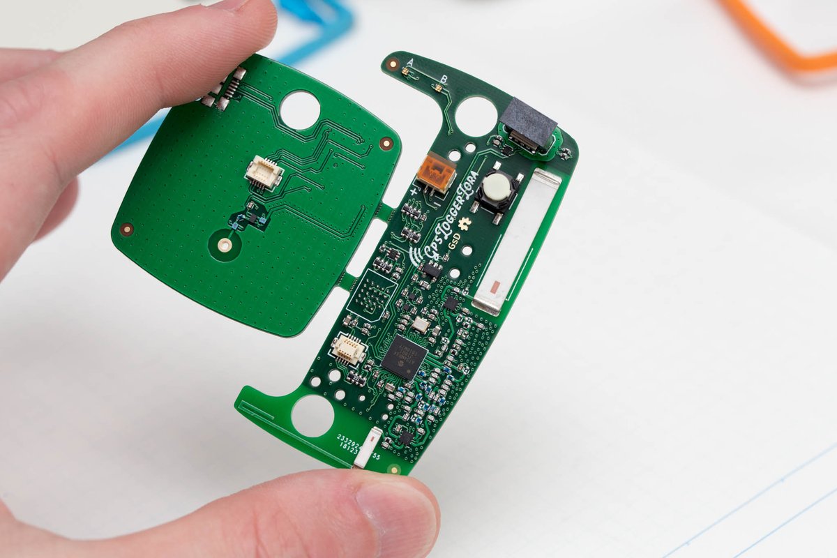
Main components on the GpsLoggerLoRa
GpsLoggerLoRa bill of materials (BOM)
110 components, 50 distinct parts.
| Qty | Part | Footprint | Refs |
|---|---|---|---|
| 2 | SKY13373 | QFN-12-1EP_3x3mm_P0.5mm_EP1.65x1.65mm | U1, U4 |
| 1 | MCP73832 | SOT-23-5 | U2 |
| 2 | NCP167 | X2SON_4_1.0x1.0mm | U3, U6 |
| 1 | MT25QL256ABA8E12 | T-PBGA-24_6.0x8.0mm_Layout5x5_P1.0mm | U5 |
| 1 | NUP2114 | SOT-553 | U7 |
| 1 | ATSAMR34J18B | TFBGA-64_6.0x6.0mm_Layout8x8_P0.65mm | U8 |
| 1 | pkl_ANTENNA | 0900AT43A0070 - 900MHz Wide band ISM Chip Antenna | A1 |
| 1 | pkl_ANTENNA | 0433AT62A0020 - 433MHz 25x5x1mm chip antenna | A2 |
| 1 | FG6943010R | SOT-666 | Q1 |
| 1 | 32.768kHz | ABS05_32.768KHz Crystal | Y1 |
| 1 | USB_C_Receptacle | usbc_vert_10132328 | J1 |
| 1 | JST GH | BM02B-GHS-TBT | J2 |
| 1 | DF12 - 10P | DF12(3.0)-10DP-0.5V(86) | J3 |
| 1 | TYETBCSANF-32.000000 | Oscilator_2.5x2.0 | OSC1 |
| 1 | SW_Push | EVQ_switch | SW1 |
| 2 | LED_ARGB | 0404LED_RGB | D1, D2 |
| 1 | 18nH | L_0402 | L1 |
| 3 | 2.2nH | L_0402 | L2, L10, L22 |
| 2 | 33nH | L_0402 | L3, L4 |
| 1 | 82nH | L_0402 | L6 |
Show 30 more
| Qty | Part | Footprint | Refs |
|---|---|---|---|
| 1 | 15nH | L_0402 | L7 |
| 1 | 12nH | L_0402 | L8 |
| 1 | 0R | L_0402 | L9 |
| 2 | 11nH | L_0402 | L11, L12 |
| 6 | 10nH | L_0402 | L13, L14, L15, L16, L23, L24 |
| 5 | 1k | L_0402 | L17, L18, L19, L20, L21 |
| 14 | 100nF | C_0402 | C1, C2, C3, C6, C11, C15, C32, C44 +6 |
| 5 | 4.7pF | C_0402 | C4, C22, C27, C57, C59 |
| 6 | DNP | C_0402 | C5, C21, C28, C29, C35, C39 |
| 5 | 3.9pF | C_0402 | C7, C8, C18, C36, C40 |
| 1 | 10n | C_0402 | C9 |
| 3 | 22pF | C_0402 | C10, C13, C34 |
| 4 | 18pF | C_0402 | C12, C33, C38, C51 |
| 6 | 1uF | C_0402 | C14, C16, C17, C43, C53, C58 |
| 1 | 0R | C_0402 | C19 |
| 1 | 8.2pF | C_0402 | C20 |
| 1 | 4.7nF | C_0402 | C23 |
| 2 | 6.8pF | C_0402 | C24, C26 |
| 1 | 2.7pF | C_0402 | C25 |
| 1 | 33nF | C_0402 | C30 |
| 2 | 1nF | C_0402 | C31, C42 |
| 1 | 5.6pF | C_0402 | C37 |
| 1 | 3.3pF | C_0402 | C41 |
| 2 | 10uF | C_0603 | C45, C46 |
| 2 | 10pF | C_0402 | C49, C50 |
| 1 | 1k | R_0603 | R1 |
| 3 | 100R | R_Array_Concave_4x0603 | R2, R3, R4 |
| 2 | 10k | R_0402 | R5, R7 |
| 1 | 47k | R_Array_Concave_4x0603 | R6 |
| 2 | 5.1k | R_0402 | R8, R9 |
GpsLoggerLoRa design files
The KiCad project lives in the gregdavill/gpsLoggerLora repository on GitHub; these links point at the commit this page was built from.
GpsLoggerLoRa: common questions
What microcontroller does the GpsLoggerLoRa use?
The GpsLoggerLoRa is built around the ATSAMR34J18B, from the Microchip SAM family.
How big is the GpsLoggerLoRa PCB?
The GpsLoggerLoRa measures 40.9 × 72.6 mm, has 4 copper layers and is 1.6 mm thick.
How many components are on the GpsLoggerLoRa?
110 components, from 50 distinct parts. The full bill of materials is listed on this page.
Where can I download the GpsLoggerLoRa design files?
From the gregdavill/gpsLoggerLora repository on GitHub, which has the KiCad layout; the links under Design files point to each one.
Can I use the GpsLoggerLoRa design in my own project?
Yes, under the terms of its MIT license, which gregdavill chose for the repository.
Can I test firmware for the GpsLoggerLoRa without the hardware?
Yes. HardLabs builds a simulation of the board from its netlist and BOM, so you can run and debug Microchip SAM firmware against it before you order a PCB.
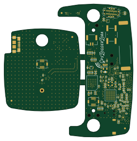
More boards in gpsLoggerLora
Similar boards
 Microchip SAM
Fpgaboy
Wren6991
50 × 50 mm89 parts4LNo license508 Microchip SAM
Kira
kiibohd
366.9 × 114.3 mm400 partsCERN-OHL-1.2415 Microchip SAM
DSKY driver
benkrasnow
43 × 92.3 mm44 partsMIT258 Microchip SAM
Duet 2 Maestro
Duet3D
100 × 123 mm336 partsCERN-OHL-1.2257 Microchip SAM
Makennbot
idlehandsdev
60 × 75 mm53 parts2LNo license175 Microchip SAM
Oxidized flash
blakesmith
61 × 21.6 mm19 parts2LNo license167