
Slot board

About the Slot board
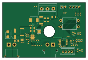
Slot board is an open source PCB design by Gultak, published on GitHub under the Apache-2.0 license. It is a 4-layer board measuring 72 × 47.5 mm, with 52 components from 48 distinct parts.
Other key parts include the LTC4162EUFD-LAD, NXP PCA9554PW (or TCA9554PWR), address 0x20, Nexperia PESD5V0S2UT and TI TLV7031DBVR (push-pull, rail-to-rail input). By type, the board carries 18 resistors, 16 capacitors, 6 connectors, 4 ICs, 3 transistors and 2 fuses.
It belongs with the power & battery designs in this gallery.
From the project
One per battery slot. It holds the LTC4162-LAD 5S Li-ion charger, the PCA9554 slot I/O (presence switch, RGB LED, bleed resistor), and the I²C and 24 V connectors. 72 × 47.5 mm, 4 layers (In1/In2 = solid GND planes), all parts on the top side. A 10 mm hole at (40.5, 25) gives scr
One per battery slot. It holds the LTC4162-LAD 5S Li-ion charger, the PCA9554 slot I/O (presence switch, RGB LED, bleed resistor), and the I²C and 24 V connectors. 72 × 47.5 mm, 4 layers (In1/In2 = solid GND planes), all parts on the top side. A 10 mm hole at (40.5, 25) gives screwdriver access to the module's rear mounting screw.
Why 4 layers? Two would work electrically, but the LTC4162 is a 1.5 MHz buck converter switching several amps: a solid GND plane directly under the top layer keeps the hot loop small, the current-sense lines quiet and the EMI low, and spreads the heat of the QFN…
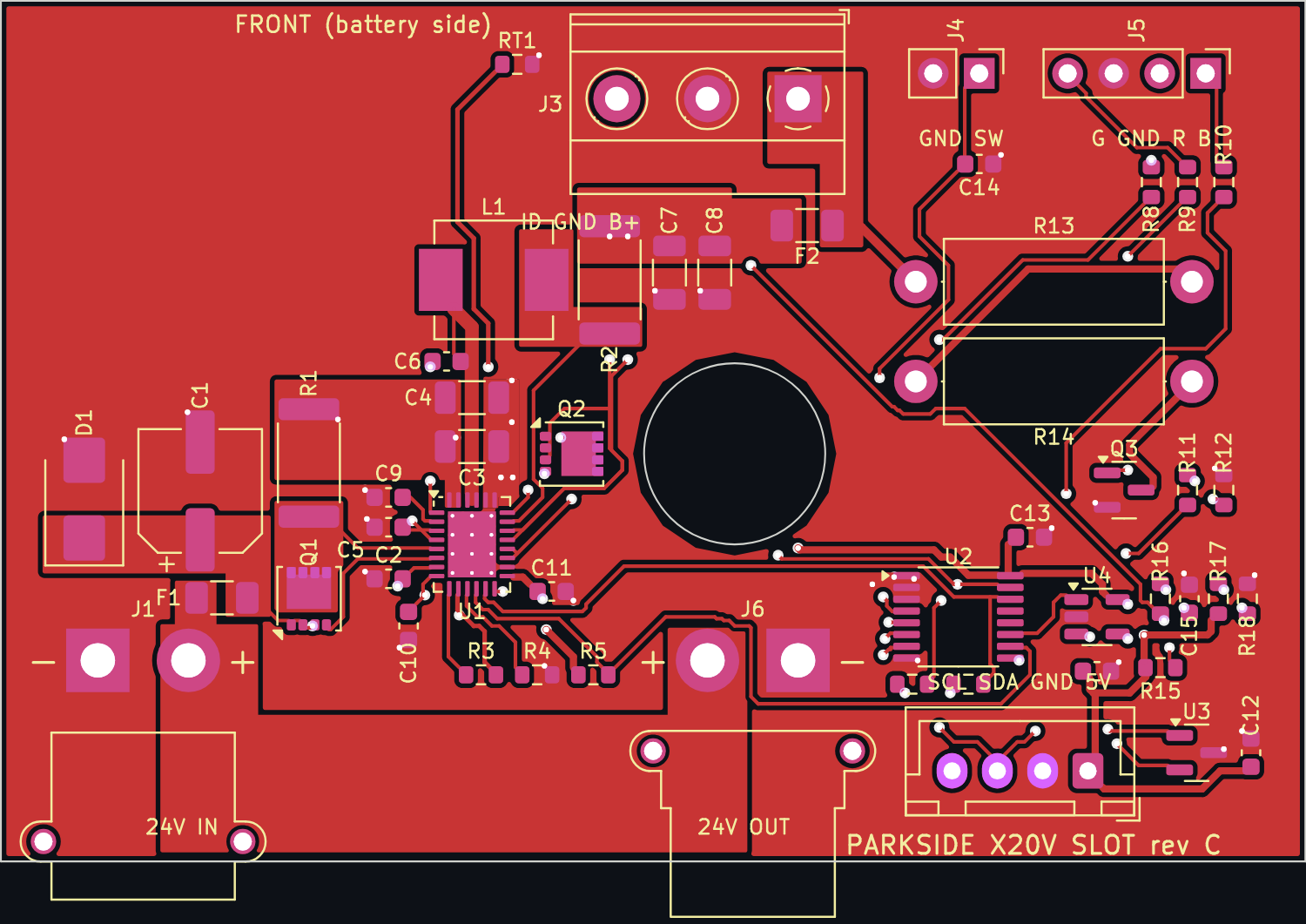
Main components on the Slot board
Slot board bill of materials (BOM)
52 components, 48 distinct parts — part numbers from the project's BOM.
| Qty | Part | Footprint | Refs |
|---|---|---|---|
| 1 | Analog Devices LTC4162EUFD-LAD#PBF (I2C adjustable!) LTC4162EUFD-LAD | QFN-28-1EP_4x5mm_P0.5mm_EP2.65x3.65mm_ThermalVias | U1 |
| 1 | NXP PCA9554PW (or TCA9554PWR), address 0x20 PCA9554PW | TSSOP-16_4.4x5mm_P0.65mm | U2 |
| 1 | Nexperia PESD5V0S2UT PESD5V0S2UT | SOT-23 | U3 |
| 1 | TI TLV7031DBVR (push-pull, rail-to-rail input) TLV7031DBV | SOT-23-5 | U4 |
| 1 | INFET, 40 V logic-level N-MOSFET (Power33). Check land pattern vs. part FDMC8327L | VSON-8_3.3x3.3mm_P0.65mm_NexFET | Q1 |
| 1 | BATFET, 40 V logic-level N-MOSFET (only powers the IC from the battery) FDMC8327L | VSON-8_3.3x3.3mm_P0.65mm_NexFET | Q2 |
| 1 | 60 V, 0.3 A 2N7002K | SOT-23 | Q3 |
| 1 | Amass XT30PW-M (male, right angle): 24 V from the previous slot / controller 24V IN | AMASS_XT30PW-M_1x02_P2.50mm_Horizontal | J1 |
| 1 | JST B4B-XH-A: 5V, GND, SDA, SCL I2C | JST_XH_B4B-XH-A_1x04_P2.50mm_Vertical | J2 |
| 1 | 5.0 mm 3-pole screw terminal (e.g. Phoenix MKDS 1,5/3-5,0 or any KF301/DG301-5.0): B+, B-, pack ID contact BATTERY | TerminalBlock_Phoenix_MKDS-1,5-3_1x03_P5.00mm_Horizontal | J3 |
| 1 | 2.54 mm pin header (Dupont cable): presence microswitch, closes to GND SWITCH | PinHeader_1x02_P2.54mm_Vertical | J4 |
| 1 | 2.54 mm pin header in the LED's lead order (Inolux INL-5TB4URGB25: 1 B, 2 R, 3 common cathode, 4 G): a straight 4-pin Dupont cable LED | PinHeader_1x04_P2.54mm_Vertical | J5 |
| 1 | Amass XT30PW-F (female, right angle): 24 V on to the next slot 24V OUT | AMASS_XT30PW-F_1x02_P2.50mm_Horizontal | J6 |
| 1 | Littelfuse 0466005.NR (1206, 5 A, very fast) 5A fast | Fuse_1206_3216Metric | F1 |
| 1 | Littelfuse 0466005.NR - mandatory, battery side 5A fast | Fuse_1206_3216Metric | F2 |
| 1 | Murata NCP18XH103F03RB (10k, B25/50 3380, 1%) 10k NTC B3380 | R_0603_1608Metric | RT1 |
| 1 | TVS 26 V unidirectional (K = pin 1) SMBJ26A | D_SMB | D1 |
| 1 | Vishay IHLP2525CZER6R8M01 (6.8 uH, IHLP-2525) 6.8u | L_Vishay_IHLP-2525 | L1 |
| 1 | Aluminium-polymer/electrolytic, low-Q damping for hot plug 47u 35V | CP_Elec_6.3x7.7 | C1 |
| 1 | X7R 100n 50V | C_0603_1608Metric | C2 |
Show 28 more
| Qty | Part | Footprint | Refs |
|---|---|---|---|
| 1 | X7R, hot-loop cap: directly at pins 27/28 - 23/24 10u 50V | C_1206_3216Metric | C3 |
| 1 | X7R 10u 50V | C_1206_3216Metric | C4 |
| 1 | X7R, VOUTA bypass 100n 50V | C_0603_1608Metric | C5 |
| 1 | X7R >= 6.3 V, BOOST cap 22n | C_0603_1608Metric | C6 |
| 1 | X7R, BATSENS+ bypass 10u 50V | C_1206_3216Metric | C7 |
| 1 | X7R, battery-side bulk 10u 50V | C_1206_3216Metric | C8 |
| 1 | X7R 4u7 10V | C_0603_1608Metric | C9 |
| 1 | X7R 1u 10V | C_0603_1608Metric | C10 |
| 1 | DVCC bypass 100n | C_0603_1608Metric | C11 |
| 1 | 5 V bulk 4u7 10V | C_0603_1608Metric | C12 |
| 1 | 100N 100n | C_0603_1608Metric | C13 |
| 1 | debounce 100n | C_0603_1608Metric | C14 |
| 1 | X5R 4u7 10V | C_0603_1608Metric | C15 |
| 1 | U4 bypass 100n | C_0603_1608Metric | C16 |
| 1 | RSNSI, 1 W current sense 10m 1% | R_2512_6332Metric | R1 |
| 1 | RSNSB, 1 W current sense 10m 1% | R_2512_6332Metric | R2 |
| 1 | NTC bias, low TC (25 ppm) 10k 0.1% | R_0603_1608Metric | R3 |
| 1 | 1.5 MHz 63k4 1% | R_0603_1608Metric | R4 |
| 1 | SMBALERT pull-up 10k | R_0603_1608Metric | R5 |
| 3 | 100 | R_0603_1608Metric | R6, R7, R11 |
| 1 | red 560 | R_0603_1608Metric | R8 |
| 1 | green 270 | R_0603_1608Metric | R9 |
| 1 | blue 270 | R_0603_1608Metric | R10 |
| 2 | 100K 100k | R_0603_1608Metric | R12, R16 |
| 2 | metal oxide 2 W, mount 2-3 mm above the board 100 2W | R_Axial_DIN0414_L11.9mm_D4.5mm_P15.24mm_Horizontal | R13, R14 |
| 1 | ID pull-up 10k | R_0603_1608Metric | R15 |
| 1 | 10K 10k | R_0603_1608Metric | R17 |
| 1 | -> 4.55 V 100k | R_0603_1608Metric | R18 |
Slot board design files
The KiCad project lives in the Gultak/parkside-charger repository on GitHub; these links point at the commit this page was built from.
Slot board: common questions
How big is the Slot board?
The Slot board measures 72 × 47.5 mm, has 4 copper layers and is 1.6 mm thick.
How many components are on the Slot board?
52 components, from 48 distinct parts, with part numbers taken from the project's own BOM. The full bill of materials is listed on this page.
Where can I download the Slot board design files?
From the Gultak/parkside-charger repository on GitHub, which has the KiCad layout, the schematic and the BOM; the links under Design files point to each one.
Can I use the Slot board design in my own project?
Yes, under the terms of its Apache-2.0 license, which Gultak chose for the repository.
More boards in parkside-charger
Similar boards

EinkPDA screen
TalismanDesign
95 × 54 mm27 parts2LApache-2.02.0k
Stack chan
stack-chan
50 × 50 mm33 parts2LApache-2.01.7k
Display Carrier
AxxAxx
35.6 × 58.2 mm5 parts2LGPL-3.01.7k
ProgrammingAdapter
stuartpittaway
10.5 × 83 mm3 parts2LCC-BY-NC-4.01.1k
TemperaturePCB PANEL
116 × 75.5 mm178 parts2LCC-BY-NC-4.01.1k
Module 16S PassiveBalanceAddOn
61 × 74 mm86 parts2LCC-BY-NC-4.01.1k