
Controller board

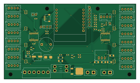
About the Controller board
Controller board is an open source ESP32 PCB design by Gultak, published on GitHub under the Apache-2.0 license. It is a 4-layer board measuring 112 × 64 mm, with 73 components from 53 distinct parts.
Its main chip is the ESP32-C6-D1, from the ESP32 family. Other key parts include the TSR 1-2450, TI TCA9548APWR, address 0x70 and TI TCA9548APWR, address 0x71. By type, the board carries 25 connectors, 25 resistors, 9 capacitors, 4 ICs, 4 transistors and 3 diodes.
It belongs with the power & battery designs in this gallery.
From the project
The controller board is the hub of the charger. It holds the xyzroe ESP32-C6 D1 in female Dupont headers, switches the 24 V for the slot chains, and runs one I²C channel to each of up to 16 slots. 112 × 64 mm (rev C), 4 layers (In1/In2 = GND), all parts on one side.
The controller board is the hub of the charger. It holds the xyzroe ESP32-C6 D1 in female Dupont headers, switches the 24 V for the slot chains, and runs one I²C channel to each of up to 16 slots. 112 × 64 mm (rev C), 4 layers (In1/In2 = GND), all parts on one side.
Why 4 layers? This board has no switching converter (the 5 V regulator is a module), so 2 layers would do. It uses 4 because the 32 slot I²C lines fan out from two TSSOP muxes on a compact board: with GND planes inside, they route on the outer layers without stitching a ground pour around them, and the 24 V band stays separate.…
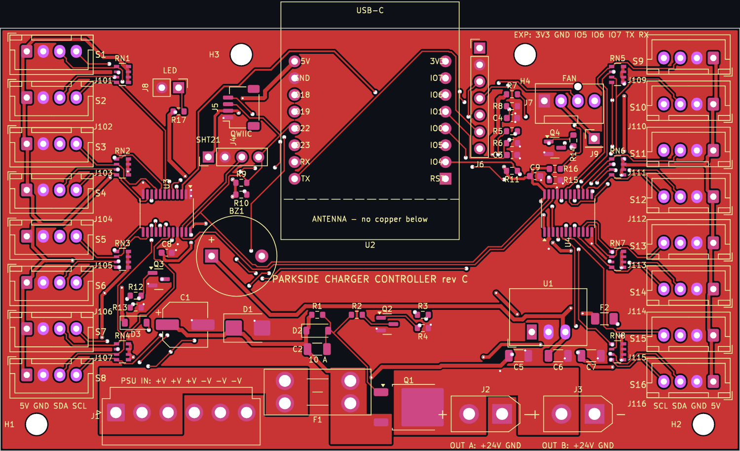
Main components on the Controller board
Controller board bill of materials (BOM)
73 components, 53 distinct parts — part numbers from the project's BOM.
| Qty | Part | Footprint | Refs |
|---|---|---|---|
| 1 | TRACO TSR 1-2450 (6.5-36 V in, 5 V 1 A) or RECOM R-78E5.0-1.0 TSR 1-2450 TRACO Power | Converter_DCDC_RECOM_R-78E-0.5_THT | U1 |
| 1 | xyzroe ESP32_C6_D1 in 2x 1x8 female Dupont headers (2.54 mm, rows 22.86 mm apart) ESP32-C6-D1 Sullins | ESP32_C6_D1_Socket | U2 |
| 1 | TI TCA9548APWR, address 0x70 TCA9548APWR NXP | TSSOP-24_4.4x7.8mm_P0.65mm | U3 |
| 1 | TI TCA9548APWR, address 0x71 TCA9548APWR NXP | TSSOP-24_4.4x7.8mm_P0.65mm | U4 |
| 1 | P-MOSFET -40 V / -40 A, 15 mOhm (or SQD40P06-15L) AOD4185 Alpha & Omega | TO-252-2 | Q1 |
| 2 | 2N7002 2N7002K Diotec | SOT-23 | Q2, Q3 |
| 1 | fan PWM, open drain 2N7002K Diotec | SOT-23 | Q4 |
| 1 | JST B6P-VH (pins 1-3 +V, 4-6 -V, as on the LOP-300 CN2) 24V PSU IN JST | JST_VH_B6P-VH_1x06_P3.96mm_Vertical | J1 |
| 1 | Amass XT30UPB-F: to the first slot of chain A (slot J1 IN) 24V OUT A Amass | AMASS_XT30UPB-F_1x02_P5.0mm_Vertical | J2 |
| 1 | Amass XT30UPB-F: to the first slot of chain B 24V OUT B Amass | AMASS_XT30UPB-F_1x02_P5.0mm_Vertical | J3 |
| 1 | SHT21 breakout (VIN GND SCL SDA), on a Dupont cable; check the order on your board SHT21 generic | PinHeader_1x04_P2.54mm_Vertical | J4 |
| 1 | Qwiic / STEMMA QT spare I2C QWIIC JST | JST_SH_SM04B-SRSS-TB_1x04-1MP_P1.00mm_Horizontal | J5 |
| 1 | spare GPIO (IO6 / IO7 are also the fan's PWM / tach) EXP generic | PinHeader_1x07_P2.54mm_Vertical | J6 |
| 1 | 4-pin PC fan header (Molex 47053-1000 or KF2510-4A) FAN Molex | FanPinHeader_1x04_P2.54mm_Vertical | J7 |
| 1 | 2-pin header: power LED (Lumex SSI-LXMP059ID), anode on pin 1 PWR LED generic | PinHeader_1x02_P2.54mm_Vertical | J8 |
| 1 | 1-pin header: +12 V aux from the PSU's fan connector 12V FAN IN generic | PinHeader_1x01_P2.54mm_Vertical | J9 |
| 1 | slot 1 I2C (JST B4B-XH-A) SLOT 1 JST | JST_XH_B4B-XH-A_1x04_P2.50mm_Vertical | J101 |
| 1 | slot 2 I2C (JST B4B-XH-A) SLOT 2 JST | JST_XH_B4B-XH-A_1x04_P2.50mm_Vertical | J102 |
| 1 | slot 3 I2C (JST B4B-XH-A) SLOT 3 JST | JST_XH_B4B-XH-A_1x04_P2.50mm_Vertical | J103 |
| 1 | slot 4 I2C (JST B4B-XH-A) SLOT 4 JST | JST_XH_B4B-XH-A_1x04_P2.50mm_Vertical | J104 |
Show 33 more
| Qty | Part | Footprint | Refs |
|---|---|---|---|
| 1 | slot 5 I2C (JST B4B-XH-A) SLOT 5 JST | JST_XH_B4B-XH-A_1x04_P2.50mm_Vertical | J105 |
| 1 | slot 6 I2C (JST B4B-XH-A) SLOT 6 JST | JST_XH_B4B-XH-A_1x04_P2.50mm_Vertical | J106 |
| 1 | slot 7 I2C (JST B4B-XH-A) SLOT 7 JST | JST_XH_B4B-XH-A_1x04_P2.50mm_Vertical | J107 |
| 1 | slot 8 I2C (JST B4B-XH-A) SLOT 8 JST | JST_XH_B4B-XH-A_1x04_P2.50mm_Vertical | J108 |
| 1 | slot 9 I2C (JST B4B-XH-A) SLOT 9 JST | JST_XH_B4B-XH-A_1x04_P2.50mm_Vertical | J109 |
| 1 | slot 10 I2C (JST B4B-XH-A) SLOT 10 JST | JST_XH_B4B-XH-A_1x04_P2.50mm_Vertical | J110 |
| 1 | slot 11 I2C (JST B4B-XH-A) SLOT 11 JST | JST_XH_B4B-XH-A_1x04_P2.50mm_Vertical | J111 |
| 1 | slot 12 I2C (JST B4B-XH-A) SLOT 12 JST | JST_XH_B4B-XH-A_1x04_P2.50mm_Vertical | J112 |
| 1 | slot 13 I2C (JST B4B-XH-A) SLOT 13 JST | JST_XH_B4B-XH-A_1x04_P2.50mm_Vertical | J113 |
| 1 | slot 14 I2C (JST B4B-XH-A) SLOT 14 JST | JST_XH_B4B-XH-A_1x04_P2.50mm_Vertical | J114 |
| 1 | slot 15 I2C (JST B4B-XH-A) SLOT 15 JST | JST_XH_B4B-XH-A_1x04_P2.50mm_Vertical | J115 |
| 1 | slot 16 I2C (JST B4B-XH-A) SLOT 16 JST | JST_XH_B4B-XH-A_1x04_P2.50mm_Vertical | J116 |
| 1 | 12 mm active buzzer 5 V 5V active Same Sky | Buzzer_12x9.5RM7.6 | BZ1 |
| 1 | Keystone 3568 holder + 10 A mini blade fuse 10A mini blade Keystone | Fuseholder_Blade_Mini_Keystone_3568 | F1 |
| 1 | Bourns MF-NSMF050 - slot 5 V rail 0.5A PTC Littelfuse | Fuse_1206_3216Metric | F2 |
| 1 | TVS 26 V SMBJ26A Vishay | D_SMB | D1 |
| 1 | Vgs clamp 12 V BZT52C12 onsemi | D_SOD-123 | D2 |
| 1 | MMSD4148T1G 1N4148W onsemi | D_SOD-123 | D3 |
| 1 | UUD1V470MCL1GS 47u 35V Nichicon | CP_Elec_6.3x7.7 | C1 |
| 1 | soft start: slow turn-on into the slot capacitors 1u 50V NIC Components | C_1206_3216Metric | C2 |
| 4 | GRT188R71H104KE13D 100n Murata | C_0603_1608Metric | C3, C4, C8, C9 |
| 1 | CL31B106KBHNNNE 10u 50V Samsung | C_1206_3216Metric | C5 |
| 2 | CL31B226KPHNNNE 22u 10V Samsung | C_1206_3216Metric | C6, C7 |
| 1 | gate pull-up (off) 100k Yageo | R_0603_1608Metric | R1 |
| 1 | RC0603FR-0747KL 47k Yageo | R_0603_1608Metric | R2 |
| 3 | RK73H1JTTD1000F 100 KOA Speer | R_0603_1608Metric | R3, R12, R14 |
| 1 | default off while the ESP boots / resets 100k Yageo | R_0603_1608Metric | R4 |
| 4 | RC0603FR-07100KL 100k Yageo | R_0603_1608Metric | R5, R7, R13, R15 |
| 3 | ERJ-3EKF1002V 10k Panasonic | R_0603_1608Metric | R6, R8, R11 |
| 2 | CRCW06034K70FKEA 4k7 Vishay | R_0603_1608Metric | R9, R10 |
| 1 | fan tach pull-up 10k Panasonic | R_0603_1608Metric | R16 |
| 1 | power LED, about 9 mA 330 Yageo | R_0603_1608Metric | R17 |
| 8 | slot bus pull-ups 4k7 x4 Panasonic | R_Array_Convex_4x0603 | RN1, RN2, RN3, RN4, RN5, RN6, RN7, RN8 |
Controller board design files
The KiCad project lives in the Gultak/parkside-charger repository on GitHub; these links point at the commit this page was built from.
Controller board: common questions
What microcontroller does the Controller board use?
The Controller board is built around the ESP32-C6-D1, from the ESP32 family.
How big is the Controller board?
The Controller board measures 112 × 64 mm, has 4 copper layers and is 1.6 mm thick.
How many components are on the Controller board?
73 components, from 53 distinct parts, with part numbers taken from the project's own BOM. The full bill of materials is listed on this page.
Where can I download the Controller board design files?
From the Gultak/parkside-charger repository on GitHub, which has the KiCad layout, the schematic and the BOM; the links under Design files point to each one.
Can I use the Controller board design in my own project?
Yes, under the terms of its Apache-2.0 license, which Gultak chose for the repository.
Can I test firmware for the Controller board without the hardware?
Yes. HardLabs builds a simulation of the board from its netlist and BOM, so you can run and debug ESP32 firmware against it before you order a PCB.
More boards in parkside-charger
Similar boards
 ESP32
OSO-BOOK-B1
joeycastillo
85 × 115 mm65 parts2LCC-BY-SA-4.08.1k ESP32
Powertrain
byrantech
64 × 45.4 mm171 parts4LMIT4.3k ESP32
Badge
atopile
56.3 × 39 mm239 parts4LMIT4.0k ESP32
Esp32 minimal
36.2 × 26.8 mm20 parts2LMIT4.0k ESP32
Controller
StuckAtPrototype
29 × 74 mm58 parts4LApache-2.03.8k ESP32
Racer
36 × 50.2 mm70 parts4LApache-2.03.8k