
TTL-to-RGB

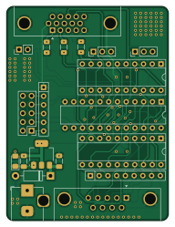
About the TTL-to-RGB PCB
TTL-to-RGB is an open source PCB design by hkzlab, published on GitHub under the CC-BY-NC-4.0 license. It is a 4-layer board measuring 47 × 62.2 mm, with 31 components from 19 distinct parts.
Other key parts include the GAL20V8, 74LS244 and AMS1117-5.0. By type, the board carries 11 resistors, 9 capacitors, 4 ICs, 4 connectors, 2 diodes and 1 jumper.
It belongs with the retro computing designs in this gallery.
From the project
This board converts CGA/EGA/MDA/Hercules TTL signals into analog RGB signals that can be fed into a compatible monitor
This board converts CGA/EGA/MDA/Hercules TTL signals into analog RGB signals that can be fed into a compatible monitor.
Depending on jumper settings, it can automatically detect MDA/Hercules and Hi-res EGA modes (uses vsync polarity detection), can be forced into low-res 64 colors EGA and can perform the "brown-fix" for CGA.
The board uses a GAL20V8 PLD to implement the conversions, sync polarity detection, brown-fix, etc.
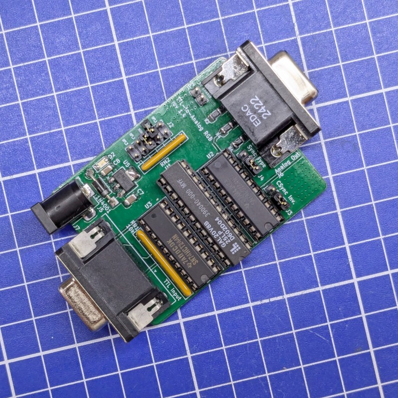
Main components on the TTL-to-RGB
TTL-to-RGB bill of materials (BOM)
31 components, 19 distinct parts.
| Qty | Part | Footprint | Refs |
|---|---|---|---|
| 1 | GAL20V8 | DIP-24_W7.62mm | U1 |
| 2 | 74LS244 | DIP-20_W7.62mm_Socket | U2, U3 |
| 1 | AMS1117-5.0 | SOT-223-3_TabPin2 | U5 |
| 1 | Options | PinHeader_2x05_P2.54mm_Vertical | J2 |
| 1 | CSync Inv. | PinHeader_1x03_P2.54mm_Vertical | J3 |
| 1 | Sync Type | PinHeader_1x03_P2.54mm_Vertical | J4 |
| 1 | Barrel_Jack | BarrelJack_Horizontal | J7 |
| 1 | 5V on video | PinHeader_1x02_P2.54mm_Vertical | JP1 |
| 1 | 1N4001 | D_DO-41_SOD81_P10.16mm_Horizontal | D1 |
| 1 | Power | LED_1206_3216Metric_Pad1.42x1.75mm_HandSolder | D2 |
| 3 | 22p | C_1206_3216Metric_Pad1.33x1.80mm_HandSolder | C1, C2, C3 |
| 3 | 100nF | C_1206_3216Metric_Pad1.33x1.80mm_HandSolder | C4, C5, C6 |
| 3 | 10u | C_1206_3216Metric_Pad1.33x1.80mm_HandSolder | C7, C8, C9 |
| 4 | 470 | R_1206_3216Metric_Pad1.30x1.75mm_HandSolder | R2, R4, R6, R10 |
| 3 | 680 | R_1206_3216Metric_Pad1.30x1.75mm_HandSolder | R3, R5, R7 |
| 1 | 1-4.7k | R_1206_3216Metric_Pad1.30x1.75mm_HandSolder | R11 |
| 1 | 10k | R_1206_3216Metric_Pad1.30x1.75mm_HandSolder | R12 |
| 1 | 10k | R_Array_SIP9 | RN1 |
| 1 | 10k | R_Array_SIP6 | RN2 |
TTL-to-RGB design files
The KiCad project lives in the hkzlab/TTL-to-RGB repository on GitHub; these links point at the commit this page was built from.
- LayoutPCB/TTL2ANALOG.kicad_pcb
- SchematicPCB/TTL2ANALOG.kicad_sch
TTL-to-RGB: common questions
How big is the TTL-to-RGB PCB?
The TTL-to-RGB measures 47 × 62.2 mm, has 4 copper layers and is 1.6 mm thick.
How many components are on the TTL-to-RGB?
31 components, from 19 distinct parts. The full bill of materials is listed on this page.
Where can I download the TTL-to-RGB design files?
From the hkzlab/TTL-to-RGB repository on GitHub, which has the KiCad layout and the schematic; the links under Design files point to each one.
Can I use the TTL-to-RGB design in my own project?
It is published under CC-BY-NC-4.0, which limits how it may be reused; read the license before building on it.
Similar boards
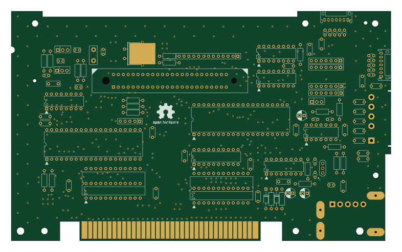
OpenTendo
Redherring32
196.3 × 118.7 mm93 parts2LTAPR-OHL-1.0850
MCL86jr
MicroCoreLabs
56.1 × 57.1 mm66 parts4LNo license532
24pin flex interposer
Wren6991
29 × 32 mm3 parts2LNo license508
Sram dev board
50 × 50 mm12 parts2LNo license508
TRS-80 Color Computer 3
baldengineer
280 × 155.3 mm204 parts2LCC-BY-4.0442
Commodore Plus 4
284.7 × 158.9 mm212 parts2LCC-BY-4.0442