
PicoDSO

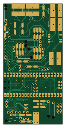
About the PicoDSO PCB
PicoDSO is an open source RP2040/RP2350 PCB design by HL65536, published on GitHub under the AGPL-3.0 license. It is a 2-layer board measuring 50.9 × 104.5 mm, with 65 components from 36 distinct parts.
Its main chip is the Pico, from the RP2040/RP2350 family. Other key parts include the optional_externalVREF, ST7789, SSD1306_Display1, SSD1306_Display2 and ADS830E. By type, the board carries 19 capacitors, 18 resistors, 10 connectors, 7 ICs, 7 switches and 3 jumpers.
It belongs with the test & measurement and displays & leds designs in this gallery.
From the project
Oscilloscope based on the Raspberry Pi Pico
Open-Source Oscilloscope based on the Raspberry Pi Pico
The minimum viable product is ready, and development of new features is ongoing. Updates will be published regularly, although the pace may be slow.
Flexible Data Acquisition: Use either the internal ADC(s) of the Raspberry Pi Pico to measure up to ~2MSa/s or 1-2 faster external ADCs (requires a custom PCB) for >50MSa/s at 8 bit. Optional PCB: The project can be built on a breadboard or with an optional PCB for easier assembly and improved performance. Display Options**: Supports both SSD1306 and ST7789 displays, with potential support…
Main components on the PicoDSO
PicoDSO bill of materials (BOM)
65 components, 36 distinct parts.
| Qty | Part | Footprint | Refs |
|---|---|---|---|
| 1 | optional_externalVREF | universalMixed | U1 |
| 1 | Pico | RPi_Pico_SMD_TH | U2 |
| 1 | ST7789 | PinHeader_1x07_P2.54mm_Vertical | U3 |
| 1 | SSD1306_Display1 | PinSocket_1x04_P2.54mm_Vertical | U4 |
| 1 | SSD1306_Display2 | PinSocket_1x04_P2.54mm_Vertical | U5 |
| 2 | ADS830E | QSOP-20 hand solder | U6, U8 |
| 1 | internalADC_GND | SolderWire-0.5sqmm_1x01_D0.9mm_OD2.1mm_Relief | J1 |
| 1 | chip1_probe+ | SolderWire-0.5sqmm_1x01_D0.9mm_OD2.1mm_Relief | J2 |
| 2 | probeGND | SolderWire-0.5sqmm_1x01_D0.9mm_OD2.1mm_Relief | J3, J5 |
| 1 | chip0_probe+ | SolderWirePad_1x01_SMD_5x10mm | J4 |
| 3 | probeConnector | SolderWire-0.5sqmm_1x01_D0.9mm_OD2.1mm_Relief | J6, J7, J8 |
| 1 | bat_GND | SolderWire-0.5sqmm_1x01_D0.9mm_OD2.1mm_Relief | J9 |
| 1 | bat+ | SolderWire-0.5sqmm_1x01_D0.9mm_OD2.1mm_Relief | J10 |
| 1 | internalADC_rangeselJumper | PinHeader_1x03_P2.54mm_Vertical | JP1 |
| 1 | ADS830E_0_rangesel | universalMixed | JP2 |
| 1 | ADS830E_1_rangesel | universalMixed | JP3 |
| 1 | ADS830E_rangesel | DIP-4_W7.62mm | SW1 |
| 1 | JoystickSwitch | JoystickSwitch | SW2 |
| 1 | dir2_alt | universalButton | SW3 |
| 1 | dir4_alt | universalButton | SW4 |
Show 16 more
| Qty | Part | Footprint | Refs |
|---|---|---|---|
| 1 | dir3_alt | universalButton | SW5 |
| 1 | dir1_alt | universalButton | SW6 |
| 1 | button | universalButton | SW7 |
| 1 | D_Schottky | universalMixedDiode | D1 |
| 10 | 100nF | universalMixed | C1, C2, C3, C8, C11, C13, C14, C15 +2 |
| 2 | 10µF | universalMixedElectrolyticCap | C7, C19 |
| 2 | Cdiv_bot | universalMixed | C9, C21 |
| 2 | Cdiv_top | universalMixed | C12, C24 |
| 3 | 68pF | universalMixed | C25, C26, C27 |
| 2 | Rdiv_bot | universalMixedLong | R3, R7 |
| 2 | Rdiv_top | universalMixedLong | R4, R8 |
| 2 | 470 | universalMixedLong | R9, R10 |
| 2 | 4.7k | universalMixedLong | R11, R12 |
| 1 | 1k | universalMixedLong | R13 |
| 6 | 22k | universalMixedLong | R14, R15, R17, R18, R20, R21 |
| 3 | 100k | universalMixedLong | R16, R19, R22 |
PicoDSO design files
The KiCad project lives in the HL65536/picoDSO repository on GitHub; these links point at the commit this page was built from.
PicoDSO: common questions
What microcontroller does the PicoDSO use?
The PicoDSO is built around the Pico, from the RP2040/RP2350 family.
How big is the PicoDSO PCB?
The PicoDSO measures 50.9 × 104.5 mm, has 2 copper layers and is 1.6 mm thick.
How many components are on the PicoDSO?
65 components, from 36 distinct parts. The full bill of materials is listed on this page.
Where can I download the PicoDSO design files?
From the HL65536/picoDSO repository on GitHub, which has the KiCad layout and the schematic; the links under Design files point to each one.
Can I use the PicoDSO design in my own project?
Yes, under the terms of its AGPL-3.0 license, which HL65536 chose for the repository.
Can I test firmware for the PicoDSO without the hardware?
Yes. HardLabs builds a simulation of the board from its netlist and BOM, so you can run and debug RP2040/RP2350 firmware against it before you order a PCB.
Similar boards
 RP2040/RP2350
Open Book Abridged Edition
joeycastillo
85 × 115 mm29 parts2LCC-BY-SA-4.08.1k RP2040/RP2350
Corne
foostan
277.2 × 107.5 mm164 parts2LCC-BY-4.07.7k RP2040/RP2350
Corne
277.2 × 107.5 mm164 parts2LCC-BY-4.07.7k RP2040/RP2350
Jitx design
gusmanb
55.5 × 65 mm26 parts4LGPL-3.05.0k RP2040/RP2350
LogicAnalyzer
57 × 55.2 mm6 parts2LGPL-3.05.0k RP2040/RP2350
Main
google
98 × 71 mm102 parts2LApache-2.02.9k