
Calibration board

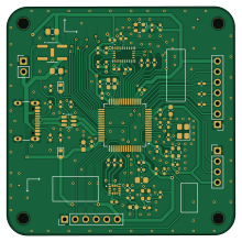
About the Calibration board
Calibration board is an open source STM32 PCB design by htl-stp-ecer, published on GitHub. It is a 2-layer board measuring 54.9 × 55 mm, with 74 components from 31 distinct parts.
Its main chip is the STM32F722RETx, from the STM32 family. Other key parts include the XC6210B332PR-G, USBLC6-2SC6, BNO086 and ICM-42688-P. By type, the board carries 32 resistors, 24 capacitors, 7 connectors, 5 ICs, 4 crystals and 2 diodes.
It belongs with the sensors designs in this gallery.
From the project
Wombat companion board — absolute position from optical flow and a reference IMU for calibrating the onboard one, enabling motion teach-in and automated setup routines
A companion board for the KIPR Wombat: absolute position from optical flow, and a reference IMU good enough to calibrate the Wombat's own.
KiCad PCB · STM32F722 firmware · On-board Madgwick fusion · Persistent flash calibration · USB-CDC to LCM bridge
There are two things a Wombat can't tell you well on its own.
The first is where it actually is. Wheel odometry integrates encoder ticks and trusts them, but wheels slip on seams, on poms and on ramps, and every slipped tick stays in the estimate for the rest of the run. Encoders measure the wheels, not the ground.
Main components on the Calibration board
Calibration board bill of materials (BOM)
74 components, 31 distinct parts.
| Qty | Part | Footprint | Refs |
|---|---|---|---|
| 1 | XC6210B332PR-G | SOT-89-5_Handsoldering | U101 |
| 1 | USBLC6-2SC6 | SOT-23-6 | U102 |
| 1 | STM32F722RETx | LQFP-64_10x10mm_P0.5mm | U201 |
| 1 | BNO086 | BNO086 | U401 |
| 1 | ICM-42688-P | ICM-42688-p | U501 |
| 1 | Crystal_GND24 | Crystal_SMD_Abracon_ABM8G-4Pin_3.2x2.5mm | Y101 |
| 3 | ECS-327KE | Oscillator_SMD_ECS_2520MV-xxx-xx-4Pin_2.5x2.0mm | Y203, Y401, Y501 |
| 1 | USB_C_Receptacle_USB2.0_16P | USB_C_Receptacle_GCT_USB4105-xx-A_16P_TopMnt_Horizontal | J101 |
| 1 | Conn_01x02_Pin | PinHeader_1x02_P2.54mm_Vertical | J102 |
| 1 | DNP | R_0805_2012Metric_Pad1.20x1.40mm_HandSolder | J201 |
| 1 | Conn_01x06_Pin | PinHeader_1x06_P2.54mm_Vertical | J501 |
| 1 | Conn_01x07_Pin | PinHeader_1x07_P2.54mm_Vertical | J601 |
| 1 | Conn_01x10_Pin | PinHeader_1x10_P1.27mm_Vertical_SMD_Pin1Right | J702 |
| 1 | Conn_01x04_Pin | PinHeader_1x04_P2.54mm_Vertical | J703 |
| 2 | LED | LED_0603_1608Metric | D101, D201 |
| 2 | 1u | C_0805_2012Metric_Pad1.18x1.45mm_HandSolder | C101, C102 |
| 11 | 100n | 0402_1005Metric_Pad0.74x0.62mm_HandSolder | C201, C202, C203, C204, C205, C207, C209, C401 +3 |
| 2 | 4u7 | C_0603_1608Metric_Pad1.08x0.95mm_HandSolder | C206, C214 |
| 1 | 1u | C_0603_1608Metric_Pad1.08x0.95mm_HandSolder | C208 |
| 2 | 27p | 0402_1005Metric_Pad0.74x0.62mm_HandSolder | C210, C211 |
Show 11 more
| Qty | Part | Footprint | Refs |
|---|---|---|---|
| 4 | 10n | 0402_1005Metric_Pad0.74x0.62mm_HandSolder | C212, C404, C501, C504 |
| 1 | DNP | C_0603_1608Metric_Pad1.08x0.95mm_HandSolder | C213 |
| 1 | 2.2u | C_0603_1608Metric | C502 |
| 2 | 5k1 | 0402_1005Metric_Pad0.74x0.62mm_HandSolder | R101, R102 |
| 2 | 1k | 0402_1005Metric_Pad0.74x0.62mm_HandSolder | R103, R207 |
| 2 | 2k2 | 0402_1005Metric_Pad0.74x0.62mm_HandSolder | R104, R105 |
| 7 | 10k | 0402_1005Metric_Pad0.74x0.62mm_HandSolder | R201, R202, R205, R407, R408, R409, R410 |
| 12 | 0R | 0402_1005Metric_Pad0.74x0.62mm_HandSolder | R203, R402, R403, R405, R406, R501, R502, R503 +4 |
| 1 | 4k7 | 0402_1005Metric_Pad0.74x0.62mm_HandSolder | R204 |
| 5 | DNP | 0402_1005Metric_Pad0.74x0.62mm_HandSolder | R206, R401, R404, R504, R506 |
| 1 | 0.1R | 0402_1005Metric_Pad0.74x0.62mm_HandSolder | R208 |
Calibration board design files
The KiCad project lives in the htl-stp-ecer/calibration-board repository on GitHub; these links point at the commit this page was built from.
Calibration board: common questions
What microcontroller does the Calibration board use?
The Calibration board is built around the STM32F722RETx, from the STM32 family.
How big is the Calibration board?
The Calibration board measures 54.9 × 55 mm, has 2 copper layers and is 1.69112 mm thick.
How many components are on the Calibration board?
74 components, from 31 distinct parts. The full bill of materials is listed on this page.
Where can I download the Calibration board design files?
From the htl-stp-ecer/calibration-board repository on GitHub, which has the KiCad layout and the schematic; the links under Design files point to each one.
Can I use the Calibration board design in my own project?
The repository has no license, so all rights stay with htl-stp-ecer. Use it as a reference, and ask the author before reusing the design.
Can I test firmware for the Calibration board without the hardware?
Yes. HardLabs builds a simulation of the board from its netlist and BOM, so you can run and debug STM32 firmware against it before you order a PCB.
Similar boards
 STM32
STM32LumenPnP Motherboard
opulo-inc
149 × 95 mm296 parts4LCC-BY-SA-4.03.7k STM32
STM32AxxSolder
AxxAxx
39 × 82.5 mm122 parts2LGPL-3.01.7k STM32
STM32AIOC
skuep
21 × 31.5 mm47 parts2LMIT1.4k STM32
STM32Ferris
pierrechevalier83
208.8 × 86.8 mm102 parts2LSHL-2.11.3k STM32
STM32176 pin board
rusefi
61.8 × 73.2 mm76 parts2LGPL-3.01.2k STM32
STM32Brain board STM32F407
61.8 × 73.2 mm69 parts2LGPL-3.01.2k