
Weather station

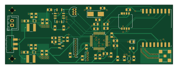
About the Weather station PCB
Weather station is an open source STM32 PCB design by Invactive, published on GitHub. It is a 2-layer board measuring 90 × 32 mm, with 59 components from 41 distinct parts.
Its main chip is the STM32F301C8T6TR, from the STM32 family. Other key parts include the RFM95W-868S2R, MICS-6814, KP254, HIH6020-021-001 and TMP36GT9Z. By type, the board carries 19 capacitors, 19 resistors, 10 ICs, 3 connectors, 2 modules and 2 diodes.
It belongs with the sensors, rf & radio and power & battery designs in this gallery.
From the project
PCB project of a remote weather station. The device can measure: temperature, air pressure, air pollution, humidity and insolation.
The PCB project was implemented on a FR-4 laminate with a thickness of 1.5mm and dimensions of 90x32mm, consisting of two signal layers.
The copper tracks have a thickness of 35μm.
The board includes a 2-pin JST-XH power connector, a programmer/debugger 8-pin connector for the microcontroller, and an SMA antenna connector.
To obtain +5V and +3.3V voltages, two voltage converters were used (with a maximum supply voltage of +5.5V).
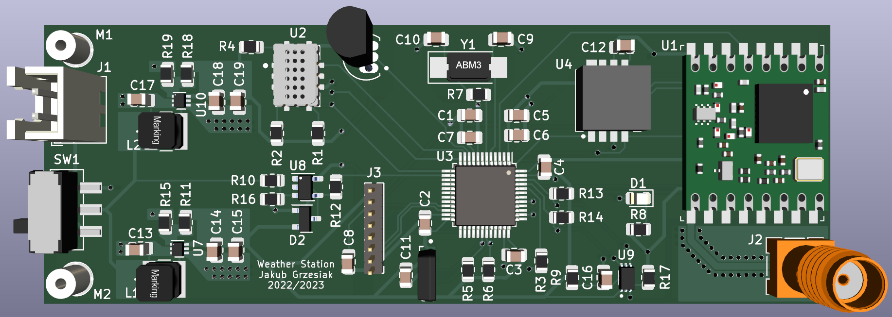
Main components on the Weather station
Weather station bill of materials (BOM)
59 components, 41 distinct parts — part numbers from the project's BOM.
| Qty | Part | Footprint | Refs |
|---|---|---|---|
| 1 | RFM95W-868S2R | HOPERF_RFM69HW | U1 |
| 1 | MICS-6814 | SENSOR_MICS-6814 | U2 |
| 1 | STM32F301C8T6TR | LQFP-48_7x7mm_P0.5mm | U3 |
| 1 | KP254 | Infineon-KP254-Manufacturer_Recommended | U4 |
| 1 | HIH6020-021-001 | Honeywell-HIH7120-021-001-Recommended_Land_Pattern_ | U5 |
| 1 | TMP36GT9Z | TO92127P521H733-3 | U6 |
| 2 | TPS61023DRLR | TPS61023DRLR | U7, U10 |
| 1 | INA180A1 | SOT-23-5 | U8 |
| 1 | BH1750FVI-TR | XDCR_BH1750FVI-TR | U9 |
| 2 | Mounting_Wuerth_WA-SMSI-M1.6_H2.5mm_9774025633 | Mounting_Wuerth_WA-SMSI-M1.6_H2.5mm_9774025633 | M1, M2 |
| 1 | ABM3-8.000MHZ-D2Y | Crystal_SMD_Abracon_ABM3-2Pin_5.0x3.2mm_HandSoldering | Y1 |
| 1 | JST-XH | JST_XH_B2B-XH-A_1x02_P2.50mm_Vertical | J1 |
| 1 | SMA Antenna Connector | MOLEX_73251-1350 | J2 |
| 1 | Programming/Debug Connector | PinHeader_1x08_P1.27mm_Vertical | J3 |
| 1 | SW_MAIN_PWR | SW_SPDT_CK-JS102011SAQN | SW1 |
| 1 | LED | LED_0805_2012Metric | D1 |
| 1 | BAT54S | SOT-23 | D2 |
| 2 | 1uH 17mR | 74404043010A | L1, L2 |
| 6 | 100nF | C_0805_2012Metric | C1, C2, C3, C4, C8, C12 |
| 1 | 4.7uF | C_0805_2012Metric | C5 |
Show 21 more
| Qty | Part | Footprint | Refs |
|---|---|---|---|
| 1 | 1uF | C_0805_2012Metric | C6 |
| 1 | 10nF | C_0805_2012Metric | C7 |
| 2 | 20pF | C_0805_2012Metric | C9, C10 |
| 1 | 0.22uF | C_0805_2012Metric | C11 |
| 1 | 2.2uF 4.06mR | C_0805_2012Metric | C13 |
| 4 | 2.2uF 7.77mR | C_0805_2012Metric | C14, C15, C18, C19 |
| 1 | 0.1uF | C_0805_2012Metric | C16 |
| 1 | 10uF 3mR | C_0805_2012Metric | C17 |
| 1 | 820R | R_0805_2012Metric | R1 |
| 1 | 27R | R_0805_2012Metric | R2 |
| 2 | 10k | R_0805_2012Metric | R3, R17 |
| 1 | 130R | R_0805_2012Metric | R4 |
| 2 | 2k2 | R_0805_2012Metric | R5, R6 |
| 1 | 390R | R_0805_2012Metric | R7 |
| 1 | 100R | R_0805_2012Metric | R8 |
| 1 | 1k | R_0805_2012Metric | R9 |
| 4 | 100k | R_0805_2012Metric | R10, R15, R16, R19 |
| 1 | 453k | R_0805_2012Metric | R11 |
| 1 | 200R | R_0805_2012Metric | R12 |
| 2 | 4k7 | R_0805_2012Metric | R13, R14 |
| 1 | 732k | R_0805_2012Metric | R18 |
Weather station design files
The KiCad project lives in the Invactive/Weather-station repository on GitHub; these links point at the commit this page was built from.
Weather station: common questions
What microcontroller does the Weather station use?
The Weather station is built around the STM32F301C8T6TR, from the STM32 family.
How big is the Weather station PCB?
The Weather station measures 90 × 32 mm, has 2 copper layers and is 1.59 mm thick.
How many components are on the Weather station?
59 components, from 41 distinct parts, with part numbers taken from the project's own BOM. The full bill of materials is listed on this page.
Where can I download the Weather station design files?
From the Invactive/Weather-station repository on GitHub, which has the KiCad layout, the schematic and the BOM; the links under Design files point to each one.
Can I use the Weather station design in my own project?
The repository has no license, so all rights stay with Invactive. Use it as a reference, and ask the author before reusing the design.
Can I test firmware for the Weather station without the hardware?
Yes. HardLabs builds a simulation of the board from its netlist and BOM, so you can run and debug STM32 firmware against it before you order a PCB.
Similar boards
 STM32
STM32LumenPnP Motherboard
opulo-inc
149 × 95 mm296 parts4LCC-BY-SA-4.03.7k STM32
STM32AxxSolder
AxxAxx
39 × 82.5 mm122 parts2LGPL-3.01.7k STM32
STM32AIOC
skuep
21 × 31.5 mm47 parts2LMIT1.4k STM32
STM32Ferris
pierrechevalier83
208.8 × 86.8 mm102 parts2LSHL-2.11.3k STM32
STM32Module 16S
stuartpittaway
71.1 × 89.6 mm113 parts4LCC-BY-NC-4.01.1k STM32
STM32Djinn
tzarc
192.3 × 150.5 mm216 parts2LCERN-OHL-S-2.0988