
RPI-PWVSA VGA, SD Card & Audio Demo Board for Pico W

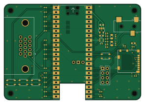
About the RPI-PWVSA VGA, SD Card & Audio Demo Board for Pico W
RPI-PWVSA VGA, SD Card & Audio Demo Board for Pico W is an open source RP2040/RP2350 PCB design by jaronbrown, published on GitHub. It is a 4-layer board measuring 74 × 52 mm, with 48 components from 29 distinct parts.
Its main chip is the PicoW, from the RP2040/RP2350 family. Other key parts include the PCM1808PWR and TPS7A8001DRBR. By type, the board carries 29 resistors, 8 capacitors, 4 connectors, 4 switches and 3 ICs.
It belongs with the audio and rf & radio designs in this gallery.
From the project
The microPython module to control the SI5351, si5351.py, was provided by https://github.com/thaaraak/Tinypico-Radio/tree/master. Some minor changes were made to the setter in order to allow individual clock enabling/disabling--used for the AM mixer local oscillator.
The microPython module to control the SI5351, si5351.py, was provided by https://github.com/thaaraak/Tinypico-Radio/tree/master. Some minor changes were made to the setter in order to allow individual clock enabling/disabling--used for the AM mixer local oscillator.
The radio control is handled by radio.py which after initializing a , can be used to parse Quisk commands and automatically control bandpass filter selection (based on frequency) and frequency. The bandpass filters can also be controlled manually by entering "BAND,AUTO" to allow for manual testing and use of the built in bypass…
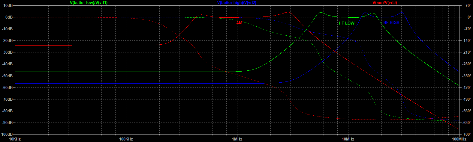
Main components on the RPI-PWVSA VGA, SD Card & Audio Demo Board for Pico W
RPI-PWVSA VGA, SD Card & Audio Demo Board for Pico W bill of materials (BOM)
48 components, 29 distinct parts — part numbers from the project's BOM.
| Qty | Part | Footprint | Refs |
|---|---|---|---|
| 1 | PCM1808PWR TLV70033_SOT23-5 | SOT-23-5 | U1 |
| 1 | PicoW | RPi_PicoW_SMD_TH | U2 |
| 1 | TPS7A8001DRBR NC7WZ16P6X | SOT-363_SC-70-6 | U3 |
| 1 | AudioJack3 | CUI_SJ-3523-audio-jack | J2 |
| 1 | Micro_SD_Card | microSD_HC_Molex_104031-0811 | J3 |
| 1 | L77HDE15SD1CH4F | DSUB-15-L77HDE15SD1CH4F | J4 |
| 1 | Conn_02x03_Odd_Even | PinHeader_2x04_P2.54mm_Vertical | J7 |
| 4 | SW_Push | SW_Push_1P1T_NO_Vertical_Wuerth_434133025816 | SW1, SW2, SW3, SW4 |
| 1 | 0.1U 1u | C_0603_1608Metric | C1 |
| 1 | 10U 1u | C_0603_1608Metric | C2 |
| 2 | 10U 100n | C_0402_1005Metric | C4, C7 |
| 1 | 100n | C_0402_1005Metric | C8 |
| 2 | 0.1U 47u | C_0805_2012Metric | C14, C15 |
| 1 | 4.7N 10u | C_0603_1608Metric | C19 |
| 2 | 10K 220 | R_0402_1005Metric | R1, R2 |
| 2 | 100 | R_0402_1005Metric | R3, R4 |
| 2 | 4.7K 1.8K | R_0402_1005Metric | R7, R8 |
| 1 | 47K DNF | R_0402_1005Metric | R9 |
| 1 | 10K 47 | R_0402_1005Metric | R10 |
| 1 | 47 | R_0402_1005Metric | R11 |
Show 9 more
| Qty | Part | Footprint | Refs |
|---|---|---|---|
| 1 | 5.1K 1k | R_0402_1005Metric | R20 |
| 1 | 10K 1k | R_0402_1005Metric | R21 |
| 4 | 1k | R_0402_1005Metric | R22, R27, R32, R37 |
| 1 | 10k | R_0402_1005Metric | R23 |
| 1 | 4.7K 10k | R_0402_1005Metric | R24 |
| 3 | 499 | R_0402_1005Metric | R26, R31, R36 |
| 3 | 2k | R_0402_1005Metric | R28, R33, R38 |
| 3 | 4.02k | R_0402_1005Metric | R29, R34, R39 |
| 3 | 8.06k | R_0402_1005Metric | R30, R35, R40 |
RPI-PWVSA VGA, SD Card & Audio Demo Board for Pico W design files
The KiCad project lives in the jaronbrown/SDR_Receiver_Design repository on GitHub; these links point at the commit this page was built from.
RPI-PWVSA VGA, SD Card & Audio Demo Board for Pico W: common questions
What microcontroller does the RPI-PWVSA VGA, SD Card & Audio Demo Board for Pico W use?
The RPI-PWVSA VGA, SD Card & Audio Demo Board for Pico W is built around the PicoW, from the RP2040/RP2350 family.
How big is the RPI-PWVSA VGA, SD Card & Audio Demo Board for Pico W?
The RPI-PWVSA VGA, SD Card & Audio Demo Board for Pico W measures 74 × 52 mm, has 4 copper layers and is 1.6 mm thick.
How many components are on the RPI-PWVSA VGA, SD Card & Audio Demo Board for Pico W?
48 components, from 29 distinct parts, with part numbers taken from the project's own BOM. The full bill of materials is listed on this page.
Where can I download the RPI-PWVSA VGA, SD Card & Audio Demo Board for Pico W design files?
From the jaronbrown/SDR_Receiver_Design repository on GitHub, which has the KiCad layout, the schematic and the BOM; the links under Design files point to each one.
Can I use the RPI-PWVSA VGA, SD Card & Audio Demo Board for Pico W design in my own project?
The repository has no license, so all rights stay with jaronbrown. Use it as a reference, and ask the author before reusing the design.
Can I test firmware for the RPI-PWVSA VGA, SD Card & Audio Demo Board for Pico W without the hardware?
Yes. HardLabs builds a simulation of the board from its netlist and BOM, so you can run and debug RP2040/RP2350 firmware against it before you order a PCB.
More boards in SDR_Receiver_Design
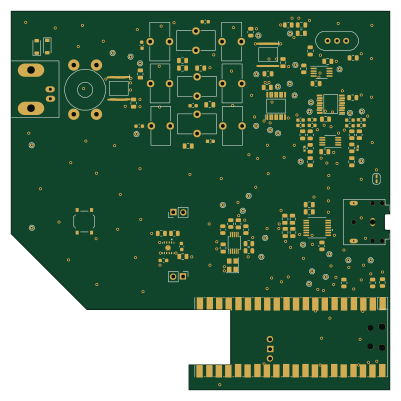
Similar boards
 RP2040/RP2350
Open Book Abridged Edition
joeycastillo
85 × 115 mm29 parts2LCC-BY-SA-4.08.1k RP2040/RP2350
Corne
foostan
277.2 × 107.5 mm164 parts2LCC-BY-4.07.7k RP2040/RP2350
Corne
277.2 × 107.5 mm164 parts2LCC-BY-4.07.7k RP2040/RP2350
LogicAnalyzer
gusmanb
57 × 55.2 mm6 parts2LGPL-3.05.0k RP2040/RP2350
Jitx design
55.5 × 65 mm26 parts4LGPL-3.05.0k RP2040/RP2350
Main
google
98 × 71 mm102 parts2LApache-2.02.9k