
ENGR357 SDR

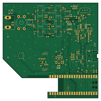
About the ENGR357 SDR PCB
ENGR357 SDR is an open source PCB design by jaronbrown, published on GitHub. It is a 4-layer board measuring 100 × 100 mm, with 128 components from 39 distinct parts.
Other key parts include the PCM1808PWR, TPS7A8001DRBR, SI5351A-B-GT, SN74CBT3253 and ADA4805-2ARMZ. By type, the board carries 41 capacitors, 33 test points, 26 resistors, 9 ICs, 9 inductors and 3 jumpers.
It belongs with the rf & radio and audio designs in this gallery.
From the project
The microPython module to control the SI5351, si5351.py, was provided by https://github.com/thaaraak/Tinypico-Radio/tree/master. Some minor changes were made to the setter in order to allow individual clock enabling/disabling--used for the AM mixer local oscillator.
The microPython module to control the SI5351, si5351.py, was provided by https://github.com/thaaraak/Tinypico-Radio/tree/master. Some minor changes were made to the setter in order to allow individual clock enabling/disabling--used for the AM mixer local oscillator.
The radio control is handled by radio.py which after initializing a , can be used to parse Quisk commands and automatically control bandpass filter selection (based on frequency) and frequency. The bandpass filters can also be controlled manually by entering "BAND,AUTO" to allow for manual testing and use of the built in bypass…
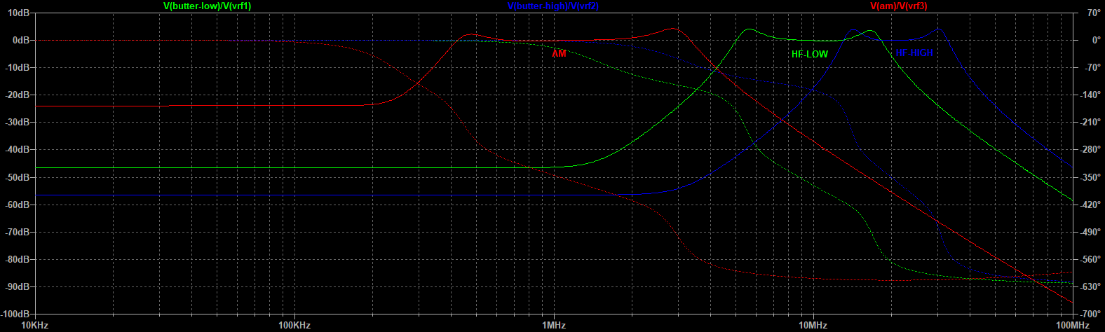
Main components on the ENGR357 SDR
ENGR357 SDR bill of materials (BOM)
128 components, 39 distinct parts — part numbers from the project's BOM.
| Qty | Part | Footprint | Refs |
|---|---|---|---|
| 1 | PCM1808PWR | PW14 | U1 |
| 1 | TPS7A8001DRBR | DRB0008A-MFG | U3 |
| 1 | SI5351A-B-GT Si5351A-B-GT | MSOP-10_3x3mm_P0.5mm | U4 |
| 4 | SN74CBT3253 | SOP65P640X120-16N | U5, U6, U7, U9 |
| 2 | ADA4805-2ARMZ | MSOP-8_3x3mm_P0.65mm | U8, U10 |
| 1 | C5210645 27Mhz 10pF | Crystal_SMD_3225-4Pin_3.2x2.5mm | Y1 |
| 1 | ECS-10.7-30A | Crystal_HC49-U-3Pin_Vertical | Y2 |
| 1 | Ant | BNC_Amphenol_B6252HB-NPP3G-50_Horizontal | J1 |
| 2 | Jumper_2_Bridged | PinHeader_1x02_P2.54mm_Vertical | JP1, JP2 |
| 1 | GND_Isolation | SolderJumper-2_P1.3mm_Open_RoundedPad1.0x1.5mm | JP3 |
| 1 | SW_Push | SW_Push_1P1T_XKB_TS-1187A | SW1 |
| 1 | Transformer_1P_1S_00 | Transformer_Toroid_Horizontal_D10.5mm_Amidon-T37 | T1 |
| 33 | TestPoint | TestPoint_THTPad_D1.0mm_Drill0.5mm | TP1, TP2, TP3, TP4, TP5, TP6, TP7, TP8 +25 |
| 2 | C8598 B5819W SL | D_SOD-123 | D1, D2 |
| 2 | 620n | L_Toroid_Vertical_L10.0mm_W5.0mm_P5.08mm | L1, L3 |
| 1 | 560n | L_Toroid_Vertical_L10.0mm_W5.0mm_P5.08mm | L2 |
| 2 | 2.7u | L_Toroid_Vertical_L10.0mm_W5.0mm_P5.08mm | L4, L6 |
| 1 | 9.1u | L_Toroid_Vertical_L10.0mm_W5.0mm_P5.08mm | L5 |
| 2 | 390n | L_Toroid_Vertical_L10.0mm_W5.0mm_P5.08mm | L7, L9 |
| 1 | 180n | L_Toroid_Vertical_L10.0mm_W5.0mm_P5.08mm | L8 |
Show 19 more
| Qty | Part | Footprint | Refs |
|---|---|---|---|
| 14 | 0.1U 0.1u | C_0805_2012Metric | C1, C3, C5, C6, C9, C11, C13, C14 +6 |
| 4 | 10U 10u | C_0805_2012Metric | C2, C4, C7, C16 |
| 1 | 0.01U 0.01u | C_0603_1608Metric | C10 |
| 1 | 4.7U 4.7u | C_0603_1608Metric | C12 |
| 8 | 4.7N 4.7n | C_0603_1608Metric | C19, C20, C21, C22, C23, C24, C25, C26 |
| 2 | 270P 270p | C_0402_1005Metric | C27, C28 |
| 2 | 1u | C_0805_2012Metric | C30, C31 |
| 3 | 470P 470p | C_0805_2012Metric | C32, C33, C34 |
| 2 | 6.8N 6.8n | C_0603_1608Metric | C35, C37 |
| 1 | 2.2N 2.2n | C_0805_2012Metric | C36 |
| 2 | 150P 150p | C_0603_1608Metric | C40, C42 |
| 1 | 330P 330p | C_0603_1608Metric | C41 |
| 5 | 10K 10k | R_0805_2012Metric | R1, R2, R10, R14, R21 |
| 11 | 0 | R_0805_2012Metric | R3, R4, R5, R6, R11, R12, R13, R15 +3 |
| 4 | 4.7K 4.7k | R_0805_2012Metric | R7, R8, R24, R25 |
| 1 | 47K 47k | R_0805_2012Metric | R9 |
| 2 | 5.1K 5.1k | R_0805_2012Metric | R19, R20 |
| 2 | 47 | R_0805_2012Metric | R22, R26 |
| 1 | 51 | R_0805_2012Metric | R23 |
ENGR357 SDR design files
The KiCad project lives in the jaronbrown/SDR_Receiver_Design repository on GitHub; these links point at the commit this page was built from.
ENGR357 SDR: common questions
How big is the ENGR357 SDR PCB?
The ENGR357 SDR measures 100 × 100 mm, has 4 copper layers and is 1.6062 mm thick.
How many components are on the ENGR357 SDR?
128 components, from 39 distinct parts, with part numbers taken from the project's own BOM. The full bill of materials is listed on this page.
Where can I download the ENGR357 SDR design files?
From the jaronbrown/SDR_Receiver_Design repository on GitHub, which has the KiCad layout, the schematic and the BOM; the links under Design files point to each one.
Can I use the ENGR357 SDR design in my own project?
The repository has no license, so all rights stay with jaronbrown. Use it as a reference, and ask the author before reusing the design.
More boards in SDR_Receiver_Design
Similar boards
KLOR
GEIGEIGEIST
160.2 × 118.3 mm79 parts2LGPL-3.01.2k
ButtonsLEDs
shanteacontrols
390 × 37 mm82 parts2LApache-2.0956
USB
52 × 12.6 mm6 parts2LApache-2.0956
Pots
390 × 93 mm75 parts2LApache-2.0956
PicoGUS Hand386
polpo
29.2 × 75.2 mm43 parts4LGPL-2.0800
Snark barker
schlae
231.1 × 106.7 mm193 parts2LNo license687