
Pjcontroller

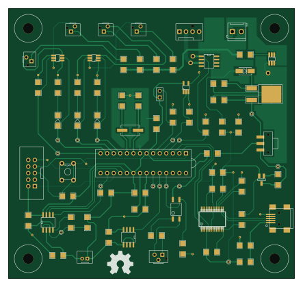
About the Pjcontroller PCB
Pjcontroller is an open source AVR/Arduino PCB design by jdeguire, published on GitHub under the GPL-3.0 license. It is a 2-layer board measuring 110.5 × 104.1 mm, with 87 components from 42 distinct parts.
Its main chip is the ATMEGA328-P, from the AVR/Arduino family. Other key parts include the VOM618A-4T, MCP3301, FT232RL, BSP762T and SN74LVC1G07. By type, the board carries 19 resistors, 15 test points, 14 capacitors, 10 ICs, 9 connectors and 5 fuses.
It belongs with the usb & debug tools designs in this gallery.
From the project
Hardware and software for controlling your homebuilt video-beaming creation.
I need to put something here, I guess...
Authors ----- Jesse DeGuire, original creator
Intro ----- This is the Projector Controller project. The goal is to provide the DIY projector community with a robust and simple means of controlling basic functionality of their DIY light-beaming creations. This includes things like monitoring temperature (and shutting the projector down if it gets too hot), controlling fan speed to keep the projector quiet, and turning the lamp on when the user presses the "On" button on the remote or OSD panel.
Main components on the Pjcontroller
Pjcontroller bill of materials (BOM)
87 components, 42 distinct parts.
| Qty | Part | Footprint | Refs |
|---|---|---|---|
| 1 | VOM618A-4T | SOP-4_LP | U1 |
| 1 | MCP3301 | SOIC8_LP | U2 |
| 1 | FT232RL | SSOP28_LP | U3 |
| 1 | BSP762T | SOIC8_LP | U4 |
| 1 | ATMEGA328-P | DIP-28_SOCK | U5 |
| 1 | SN74LVC1G07 | SOT23-5_LP | U6 |
| 1 | L78M05C | DPAK_VREG_LP | U7 |
| 2 | NUD3124 | SOT23-6_LP | U8, U10 |
| 1 | TMP36_SOIC | SOIC8_LP | U9 |
| 1 | MOSFET_P | SOT23GDS_LP | Q1 |
| 1 | RSQ045N03 | SOT23-6_LP | Q2 |
| 1 | 20MHz | XTAL_SMD | X1 |
| 1 | USB-MINI-B | USB_MINI_B_LP | CON1 |
| 1 | CONN_3 | MINI_CT_3_PTH | CON2 |
| 1 | CONN_2 | JST_PH_2_PTH | CON3 |
| 1 | 4PIN_FAN_CONN | 4PIN_FAN_PTH | CON5 |
| 4 | CONN_2 | MINI_CT_2_PTH | CON6, CON7, CON9, CON10 |
| 1 | AVR-ISP-10 | AVR_ISP_PTH | CON8 |
| 5 | 120mA | SM1206_LP | F1, F2, F3, F4, F5 |
| 1 | JUMPER-2PTH | PIN_ARRAY_2X1 | JP1 |
Show 22 more
| Qty | Part | Footprint | Refs |
|---|---|---|---|
| 4 | MNT_HOLE_NPT | MNT_HOLE_4x10mm | MH1, MH2, MH3, MH4 |
| 1 | TAC_SWITCHSMD | TACTILE-SW-PTH | S1 |
| 1 | SWITCH_INV | SWITCH_SPDT_LP | SW1 |
| 15 | TST | PINTST | TP1, TP2, TP3, TP4, TP5, TP8, TP9, TP10 +7 |
| 1 | S1M | SMA-DIODE_LP | D1 |
| 1 | Green | SM1206_DIODE_LP | D2 |
| 1 | Yellow | SM1206_DIODE_LP | D3 |
| 1 | Red | SM1206_DIODE_LP | D4 |
| 1 | INDUCTOR_SMALL | SM1206_LP | L1 |
| 1 | 10nF | SM1206_LP | C1 |
| 8 | 100nF | SM1206_LP | C2, C4, C5, C6, C7, C8, C9, C14 |
| 1 | 4.7uF | SM1206_LP | C3 |
| 1 | 10uF | SM1206_LP | C10 |
| 1 | 1uF | SM1206_LP | C11 |
| 2 | 22pF | SM1206_LP | C12, C13 |
| 3 | 3.3k | SM1206_LP | R1, R9, R19 |
| 11 | 10k | SM1206_LP | R2, R3, R4, R6, R8, R10, R12, R15 +3 |
| 1 | 20k | SM1206_LP | R5 |
| 1 | 1k | SM1206_LP | R7 |
| 1 | 470 | SM1206_LP | R11 |
| 1 | 1.5k | SM1206_LP | R13 |
| 1 | 2.2k | SM1206_LP | R14 |
Pjcontroller design files
The KiCad project lives in the jdeguire/pjcontroller repository on GitHub; these links point at the commit this page was built from.
Pjcontroller: common questions
What microcontroller does the Pjcontroller use?
The Pjcontroller is built around the ATMEGA328-P, from the AVR/Arduino family.
How big is the Pjcontroller PCB?
The Pjcontroller measures 110.5 × 104.1 mm, has 2 copper layers and is 1.6 mm thick.
How many components are on the Pjcontroller?
87 components, from 42 distinct parts. The full bill of materials is listed on this page.
Where can I download the Pjcontroller design files?
From the jdeguire/pjcontroller repository on GitHub, which has the KiCad layout; the links under Design files point to each one.
Can I use the Pjcontroller design in my own project?
Yes, under the terms of its GPL-3.0 license, which jdeguire chose for the repository.
Can I test firmware for the Pjcontroller without the hardware?
Yes. HardLabs builds a simulation of the board from its netlist and BOM, so you can run and debug AVR/Arduino firmware against it before you order a PCB.
Similar boards
 AVR/Arduino
Magspoof
samyk
35 × 29 mm11 parts2LNo license4.2k AVR/Arduino
Redox keyboard
mattdibi
162.2 × 126.5 mm77 parts2LMIT2.0k AVR/Arduino
Labrador
espotek-org
36.8 × 34.7 mm75 parts2LNo license1.2k AVR/Arduino
V4
stuartpittaway
30 × 50 mm38 parts2LCC-BY-NC-4.01.1k AVR/Arduino
ModuleV450
30 × 61.4 mm39 parts2LCC-BY-NC-4.01.1k AVR/Arduino
Discipline
coseyfannitutti
304.9 × 122.8 mm170 parts2LCC-BY-NC-4.01.0k