
ENGR357-SDR-PennockRoque

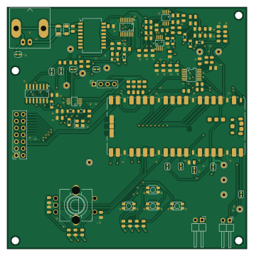
About the ENGR357-SDR-PennockRoque PCB
ENGR357-SDR-PennockRoque is an open source RP2040/RP2350 PCB design by JDPennockGB, published on GitHub. It is a 4-layer board measuring 89 × 89.5 mm, with 110 components from 41 distinct parts.
Its main chip is the C7203002, from the RP2040/RP2350 family. Other key parts include the SI5351A-B-GT, SN74AC74DR, PCM1808PWR, OPA2350EA/250 and SN74CBT3253DBQR. By type, the board carries 37 resistors, 31 capacitors, 11 test points, 10 inductors, 6 ICs and 5 connectors.
It belongs with the rf & radio, audio and displays & leds designs in this gallery.
From the project
A custom-built, high-performance Software Defined Radio (SDR) receiver powered by the Raspberry Pi Pico (RP2040). This project combines a classic hardware Tayloe detector with modern digital signal processing, streaming 24-bit I/Q audio and CAT control over a single USB cable dir
A custom-built, high-performance Software Defined Radio (SDR) receiver powered by the Raspberry Pi Pico (RP2040). This project combines a classic hardware Tayloe detector with modern digital signal processing, streaming 24-bit I/Q audio and CAT control over a single USB cable directly to PC-based SDR software like Quisk.
GitHub Link: https://github.com/JDPennockGB/ENGR357-SDR-PennockRoque
Main components on the ENGR357-SDR-PennockRoque
ENGR357-SDR-PennockRoque bill of materials (BOM)
110 components, 41 distinct parts — part numbers from the project's BOM.
| Qty | Part | Footprint | Refs |
|---|---|---|---|
| 1 | SI5351A-B-GT SKYWORKS/SILICON LABS(芯科) | MSOP-10_L3.0-W3.0-P0.50-LS5.0-BL | U1 |
| 1 | SN74AC74DR TI(德州仪器) | SOIC-14_L8.7-W3.9-P1.27-LS6.0-BL | U2 |
| 1 | PCM1808PWR TI(德州仪器) | TSSOP-14_L5.0-W4.4-P0.65-LS6.4-BL | U3 |
| 2 | OPA2350EA/250 | VSSOP-8_L3.0-W3.0-P0.65-LS5.0-BL | U4, U5 |
| 1 | SN74CBT3253DBQR TI(德州仪器) | SSOP-16_L4.9-W3.9-P0.64-LS6.0-BL | U6 |
| 1 | C7203002 RaspberryPi_Pico | RaspberryPi_Pico_SMD | A1 |
| 1 | C52204801 ASE-xxxMHz | Oscillator_SMD_Abracon_ASE-4Pin_3.2x2.5mm | Y3 |
| 1 | Antenna | BNC_Amphenol_B6252HB-NPP3G-50_Horizontal | J1 |
| 1 | OLED Header | PinSocket_1x04_P2.54mm_Vertical | J2 |
| 1 | 1x8 LCD Header | PinSocket_2x07_P2.54mm_Vertical | J3 |
| 2 | BackupVCC (+3.3v) | PinHeader_1x02_P2.54mm_Horizontal | J4, J5 |
| 4 | TS-1185-W-4P-H1.8-160 CAX(创都) | SW-SMD_4P-L3.5-W3.0-P1.50-LS4.7 | SW1, SW2, SW3, SW4 |
| 1 | EC11E18244AU ALPSALPINE(阿尔卑斯阿尔派) | SW-TH_EC11XXXXXXXX | SW5 |
| 1 | H1102NLT H1102NLT_C20623173 DEXU(德旭电子) | XFMR-SMD_H1102NLT | T2 |
| 1 | I_CLK | TestPoint_THTPad_D2.0mm_Drill1.0mm | TP1 |
| 1 | Q_CLK | TestPoint_THTPad_D2.0mm_Drill1.0mm | TP2 |
| 1 | Q_OUT | TestPoint_THTPad_D2.0mm_Drill1.0mm | TP3 |
| 1 | I_OUT | TestPoint_THTPad_D2.0mm_Drill1.0mm | TP4 |
| 1 | LO_CLK | TestPoint_THTPad_D2.0mm_Drill1.0mm | TP5 |
| 1 | +3.3V_Pico | TestPoint_THTPad_D2.0mm_Drill1.0mm | TP6 |
Show 21 more
| Qty | Part | Footprint | Refs |
|---|---|---|---|
| 1 | GND | TestPoint_THTPad_D2.0mm_Drill1.0mm | TP7 |
| 1 | I_CLK_J | TestPoint_THTPad_D2.0mm_Drill1.0mm | TP9 |
| 1 | Q_CLK_J | TestPoint_THTPad_D2.0mm_Drill1.0mm | TP10 |
| 1 | +3.3V_bus | TestPoint_THTPad_D2.0mm_Drill1.0mm | TP11 |
| 1 | +5V_bus | TestPoint_THTPad_D2.0mm_Drill1.0mm | TP12 |
| 2 | 1N4004W | D_SOD-123FL | D1, D2 |
| 10 | C1017 ~ | FB_0805 | FB11, FB12, FB13, FB14, FB15, FB16, FB17, FB18 +2 |
| 16 | 10UF 10uF | C_0805 | C1, C2, C3, C4, C9, C12, C13, C18 +8 |
| 4 | 10NF 10nF | C_0805 | C5, C6, C7, C8 |
| 2 | 47PF 47pF | C_0805 | C10, C11 |
| 2 | 1UF 1uF | C_0805 | C16, C17 |
| 5 | 100NF 100nF | C_0805 | C23, C24, C28, C30, C31 |
| 2 | 2.2NF 2.2nF | C_0805 | C25, C34 |
| 4 | 10Ω | R_0805 | R1, R2, R3, R4 |
| 2 | 47Ω | R_0805 | R5, R6 |
| 2 | 1.5kΩ | R_0805 | R7, R8 |
| 8 | 33Ω | R_0805 | R9, R10, R11, R12, R13, R14, R16, R24 |
| 2 | 470Ω | R_0805 | R15, R23 |
| 4 | 100Ω | R_0805 | R17, R18, R19, R20 |
| 2 | 4.7kΩ | R_0805 | R21, R22 |
| 13 | 10kΩ | R_0805 | R36, R37, R38, R39, R40, R41, R42, R43 +5 |
ENGR357-SDR-PennockRoque design files
The KiCad project lives in the JDPennockGB/ENGR357-SDR-PennockRoque repository on GitHub; these links point at the commit this page was built from.
- LayoutKiCad-Designs-(ROOT IS CURRENT)/ArchivedDesignsV1-3/Version 3 Tayloe Detector/SDR-v3-TayloeDetector-FINAL.kicad_pcb
- SchematicKiCad-Designs-(ROOT IS CURRENT)/ArchivedDesignsV1-3/Version 3 Tayloe Detector/SDR-v3-TayloeDetector-FINAL.kicad_sch
- BOMKiCad-Designs-(ROOT IS CURRENT)/ArchivedDesignsV1-3/Version 3 Tayloe Detector/Pennock,Roque-ENGR356-SDR-ProductionFiles/bom.csv
ENGR357-SDR-PennockRoque: common questions
What microcontroller does the ENGR357-SDR-PennockRoque use?
The ENGR357-SDR-PennockRoque is built around the C7203002, from the RP2040/RP2350 family.
How big is the ENGR357-SDR-PennockRoque PCB?
The ENGR357-SDR-PennockRoque measures 89 × 89.5 mm, has 4 copper layers and is 1.6 mm thick.
How many components are on the ENGR357-SDR-PennockRoque?
110 components, from 41 distinct parts, with part numbers taken from the project's own BOM. The full bill of materials is listed on this page.
Where can I download the ENGR357-SDR-PennockRoque design files?
From the JDPennockGB/ENGR357-SDR-PennockRoque repository on GitHub, which has the KiCad layout, the schematic and the BOM; the links under Design files point to each one.
Can I use the ENGR357-SDR-PennockRoque design in my own project?
The repository has no license, so all rights stay with JDPennockGB. Use it as a reference, and ask the author before reusing the design.
Can I test firmware for the ENGR357-SDR-PennockRoque without the hardware?
Yes. HardLabs builds a simulation of the board from its netlist and BOM, so you can run and debug RP2040/RP2350 firmware against it before you order a PCB.
Similar boards
 RP2040/RP2350
Open Book Abridged Edition
joeycastillo
85 × 115 mm29 parts2LCC-BY-SA-4.08.1k RP2040/RP2350
Corne
foostan
277.2 × 107.5 mm164 parts2LCC-BY-4.07.7k RP2040/RP2350
Corne
277.2 × 107.5 mm164 parts2LCC-BY-4.07.7k RP2040/RP2350
Jitx design
gusmanb
55.5 × 65 mm26 parts4LGPL-3.05.0k RP2040/RP2350
LogicAnalyzer
57 × 55.2 mm6 parts2LGPL-3.05.0k RP2040/RP2350
Main
google
98 × 71 mm102 parts2LApache-2.02.9k