
ServoBoard

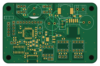
About the ServoBoard PCB
ServoBoard is an open source AVR/Arduino PCB design by jeffrey500, published on GitHub. It is a 2-layer board measuring 82.8 × 53.3 mm, with 66 components from 37 distinct parts.
Its main chip is the ATmega328PB-A, from the AVR/Arduino family. Other key parts include the LM2596SX-ADJ/NOPB, AMS1117-5.0, CH340C, OUTPUT 6N137 and INPUT 6N137. By type, the board carries 21 capacitors, 16 resistors, 12 ICs, 6 diodes, 1 crystal and 1 switch.
It belongs with the robotics & motion, power & battery and usb & debug tools designs in this gallery.
From the project
A custom PCB that drives up to 4 PWM servos. The board uses the atmega328PB and has variable input and variable servo voltage using the LM2596S buck and AMS1117 LDO. The board also has 3 6n137 optocouplers.
Note: the USB connection can only be used after initial bootloader burning (see ISP section).
Using the LM2596S buck voltage regulator, the board can utilize a maximum of 3A at the output of the Buck regulator. The efficiency of the LM2596S 92%. The board accepts a voltage range of 40V and can step it down to 1.25V-35V. You can adjust the output voltage of the LM2596S by adjusting the screw on the blue potentiometer. The potentiometer acts as a voltage divider which alters the internal PWM duty cycle.

Main components on the ServoBoard
ServoBoard bill of materials (BOM)
66 components, 37 distinct parts — part numbers from the project's BOM.
| Qty | Part | Footprint | Refs |
|---|---|---|---|
| 1 | LM2596SX-ADJ/NOPB TI(德州仪器) | TO-263-5_L10.2-W8.9-P1.70-TL | U1 |
| 1 | AMS1117-5.0 AMS | SOT-223_L6.5-W3.5-P2.30-LS7.0-BR | U2 |
| 1 | CH340C | SOIC-16_3.9x9.9mm_P1.27mm | U3 |
| 2 | OUTPUT 6N137 | DIP-8_W7.62mm_Socket | U4, U6 |
| 1 | INPUT 6N137 | DIP-8_W7.62mm_Socket | U5 |
| 1 | Power Input | CONN-TH_P5.00_KF301-5.0-2P | U7 |
| 1 | IN+ IN- | HDR-TH_2P-P2.54-V-M-3 | U9 |
| 2 | Analog Pins | HDR-TH_5P-P2.54-V-M | U10, U11 |
| 1 | ATmega328PB-A | TQFP-32_7x7mm_P0.8mm | U12 |
| 1 | Reset | HDR-TH_2P-P2.54-V-M-3 | U13 |
| 1 | 16MHz | OSC-TH_L10.0-W4.5-P5.00 | X1 |
| 1 | PWM 1 | CONN-TH_HX-PZ2.54-1X3P-ZZ | H1 |
| 1 | PWM 2 | CONN-TH_HX-PZ2.54-1X3P-ZZ | H2 |
| 1 | PWM 4 | CONN-TH_HX-PZ2.54-1X3P-ZZ | H3 |
| 1 | PWM 3 | CONN-TH_HX-PZ2.54-1X3P-ZZ | H4 |
| 2 | GND SIG VCC | CONN-TH_HX-PZ2.54-1X3P-ZZ | H5, H6 |
| 1 | Digital Pins | HDR-TH_9P-P2.54-V-F-3 | H12 |
| 1 | RESET | SW-SMD_L4.0-W2.9-LS5.0 | SW1 |
| 1 | USB-C | USB-C-SMD_TYPE-C-6PIN-2MD-073 | USB1 |
| 1 | RX | LED1206-FD | D2 |
Show 17 more
| Qty | Part | Footprint | Refs |
|---|---|---|---|
| 1 | TX | LED1206-FD | D3 |
| 1 | PWR | LED1206-FD | D4 |
| 3 | D_Schottky | SMA_L4.4-W2.8-LS5.4-R-RD | D7, D9, D10 |
| 1 | 47 uH | IND-SMD_L12.3-W12.3 | L3 |
| 1 | TAJA226K010RNJ Kyocera AVX | CASE-A_3216 | C1 |
| 3 | 0.1 uF | C_0805_2012Metric | C3, C4, C5 |
| 10 | 0.1uF | C_0805_2012Metric | C6, C7, C8, C11, C12, C13, C18, C19 +2 |
| 2 | 22pF | C_0805_2012Metric | C9, C10 |
| 2 | 330 uF | CAP-TH_BD12.5-P5.00-D0.6-FD | C14, C15 |
| 1 | 10 nF | C_0805_2012Metric | C16 |
| 1 | KM228M025J20RR0VH2FP0 2200uF 25V 13*20 Chengx(承兴) | CAP-TH_BD13.0-P5.00-D1.2-FD | C17 |
| 1 | TAJA106K016RNJ Kyocera AVX | CAP-SMD_L3.2-W1.6-RD-C7171 | C22 |
| 2 | 5.1k | R_0805_2012Metric | R1, R2 |
| 1 | 10k | R_0805_2012Metric | R3 |
| 9 | 1k | R_0805_2012Metric | R4, R5, R6, R7, R8, R12, R14, R15 +1 |
| 3 | 330 | R_0805_2012Metric | R9, R10, R11 |
| 1 | 3296W-1-103LF BOURNS | RES-ADJ-TH_3296W | R13 |
ServoBoard design files
The KiCad project lives in the jeffrey500/ServoBoard repository on GitHub; these links point at the commit this page was built from.
- LayoutServoBoard V21.kicad_pcb
- SchematicServoBoard V21.kicad_sch
- BOMServoBoard_BOM.csv
ServoBoard: common questions
What microcontroller does the ServoBoard use?
The ServoBoard is built around the ATmega328PB-A, from the AVR/Arduino family.
How big is the ServoBoard PCB?
The ServoBoard measures 82.8 × 53.3 mm, has 2 copper layers and is 1.6 mm thick.
How many components are on the ServoBoard?
66 components, from 37 distinct parts, with part numbers taken from the project's own BOM. The full bill of materials is listed on this page.
Where can I download the ServoBoard design files?
From the jeffrey500/ServoBoard repository on GitHub, which has the KiCad layout, the schematic and the BOM; the links under Design files point to each one.
Can I use the ServoBoard design in my own project?
The repository has no license, so all rights stay with jeffrey500. Use it as a reference, and ask the author before reusing the design.
Can I test firmware for the ServoBoard without the hardware?
Yes. HardLabs builds a simulation of the board from its netlist and BOM, so you can run and debug AVR/Arduino firmware against it before you order a PCB.
Similar boards
 AVR/Arduino
V4
stuartpittaway
30 × 50 mm38 parts2LCC-BY-NC-4.01.1k AVR/Arduino
ModuleV450
30 × 61.4 mm39 parts2LCC-BY-NC-4.01.1k AVR/Arduino
Easyduino Atmega Nano
Hanqaqa
43.4 × 18 mm30 parts4LCERN-OHL-P-2.0746 AVR/Arduino
Easyduino Atmega
68.8 × 53.6 mm35 parts4LCERN-OHL-P-2.0746 AVR/Arduino
UsbGpib
xyphro
54 × 15 mm21 parts2LMIT683 AVR/Arduino
Lumberjack
peej
284.7 × 94.2 mm149 parts2LMIT402