Input Board

About the Input Board
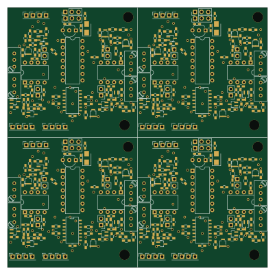
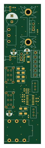
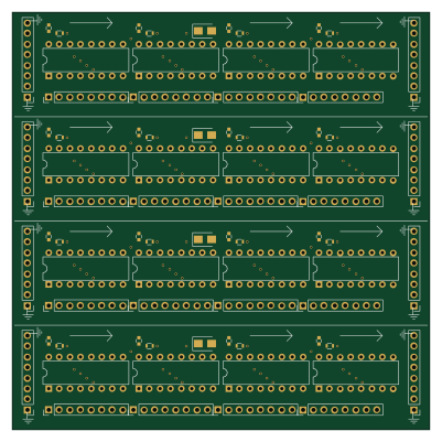
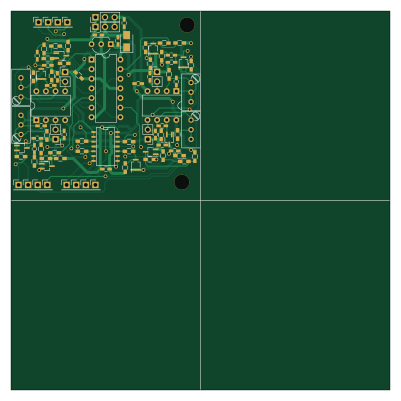
Input Board is an open source PCB design by jensenr30, published on GitHub. It is a 2-layer board measuring 100 × 100 mm, with 93 components from 31 distinct parts.
Other key parts include the TLV2374, LM7805_TO220, TL084, 74HC14 and LM833. By type, the board carries 34 resistors, 23 capacitors, 14 connectors, 9 transistors, 5 ICs and 4 inductors.
From the project
Schematics, PCBs, Simulations, ...
I usually generate .pdf files for all my schematics and Gerber files once they are finished, so I can often view my schematics and layouts without having to install KiCad or gerbv.
Main components on the Input Board
Input Board bill of materials (BOM)
93 components, 31 distinct parts — part numbers from the project's BOM.
| Qty | Part | Footprint | Refs |
|---|---|---|---|
| 1 | TLV2374 LM833 | DIP-8_W7.62mm | U1 |
| 1 | LM7805_TO220 78L05 | TO-92_Inline_Wide | U2 |
| 1 | TL084 | SOIC-14_N | U3 |
| 1 | 74HC14 | DIP-14_W7.62mm | U4 |
| 1 | LM833 | DIP-8_W7.62mm | U5 |
| 1 | STP100N8F6 BC847CW | SOT-323_SC-70_Handsoldering | Q1 |
| 8 | BC847CW | SOT-323_SC-70_Handsoldering | Q2, Q3, Q4, Q5, Q6, Q7, Q8, Q9 |
| 4 | AUDIO | Pin_Header_Straight_1x01_Pitch2.54mm | J1, J2, J7, J8 |
| 3 | ENV | Pin_Header_Straight_1x01_Pitch2.54mm | J3, J9, J10 |
| 1 | NMJ6HHD2 ENV | Pin_Header_Straight_1x01_Pitch2.54mm | J4 |
| 1 | SCREW_TERMINAL_01X06 PULSE | Pin_Header_Straight_1x01_Pitch2.54mm | J5 |
| 3 | PULSE | Pin_Header_Straight_1x01_Pitch2.54mm | J6, J11, J12 |
| 1 | Power In | Pin_Header_Straight_1x03_Pitch2.54mm | J13 |
| 1 | Power Out | Pin_Header_Straight_1x03_Pitch2.54mm | J14 |
| 3 | 100K 10k | Potentiometer_Trimmer_Bourns_3296W | RV1, RV2, RV3 |
| 1 | 10k | Potentiometer_Trimmer_Bourns_3296W | RV4 |
| 4 | Input Coil | Pin_Header_Straight_1x02_Pitch2.54mm | L1, L2, L3, L4 |
| 2 | 10U 10n | C_0603_HandSoldering | C1, C3 |
| 4 | 100N 10n | C_0603_HandSoldering | C4, C6, C7, C10 |
| 1 | 47N 10n | C_0603_HandSoldering | C8 |
Show 11 more
| Qty | Part | Footprint | Refs |
|---|---|---|---|
| 1 | 1000U 10n | C_0603_HandSoldering | C11 |
| 14 | 10n | C_0603_HandSoldering | C12, C13, C14, C15, C16, C17, C19, C20 +6 |
| 1 | 10µ | CP_Tantalum_Case-B_EIA-3528-21_Wave | C18 |
| 2 | 100K 4.7 | R_0603_HandSoldering | R1, R2 |
| 5 | 10k | R_0603_HandSoldering | R3, R4, R20, R21, R34 |
| 7 | 10M | R_0603_HandSoldering | R5, R10, R12, R22, R23, R26, R28 |
| 1 | 100 10M | R_0603_HandSoldering | R6 |
| 1 | 0 | R_0603_HandSoldering | R7 |
| 8 | 1M | R_0603_HandSoldering | R8, R9, R11, R13, R24, R25, R27, R29 |
| 8 | 100k | R_0603_HandSoldering | R14, R15, R16, R17, R30, R31, R32, R33 |
| 2 | 4.7 | R_0603_HandSoldering | R18, R19 |
Input Board design files
The KiCad project lives in the jensenr30/cad repository on GitHub; these links point at the commit this page was built from.
Input Board: common questions
How big is the Input Board?
The Input Board measures 100 × 100 mm, has 2 copper layers and is 1.6 mm thick.
How many components are on the Input Board?
93 components, from 31 distinct parts, with part numbers taken from the project's own BOM. The full bill of materials is listed on this page.
Where can I download the Input Board design files?
From the jensenr30/cad repository on GitHub, which has the KiCad layout and the BOM; the links under Design files point to each one.
Can I use the Input Board design in my own project?
The repository has no license, so all rights stay with jensenr30. Use it as a reference, and ask the author before reusing the design.