
DC710 - The Radio Bomber

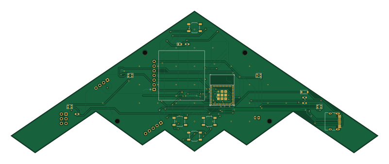
About the DC710 - The Radio Bomber PCB
DC710 - The Radio Bomber is an open source ESP32 PCB design by jeremylaratro, published on GitHub. It is a 2-layer board measuring 200 × 77.1 mm, with 56 components from 29 distinct parts.
Its main chip is the ESP32-C3-MINI-1, from the ESP32 family. Other key parts include the AP2112K-3.3, SA868-V and TP4056_Module. By type, the board carries 18 capacitors, 18 resistors, 6 diodes, 4 ICs, 4 connectors and 4 switches.
It belongs with the rf & radio, wearables and power & battery designs in this gallery.
From the project
Badge development for DefCon 710 group
ESP32-C3 + SA868-V VHF transceiver in a B-2 Spirit silhouette PCB. ~$16 BOM at qty 100, single-cell LiPo, 200×80mm flying-wing form factor (~7.87" tip-to-tip, real B-2 proportions: wingspan/length ≈ 2.5, ~31° leading-edge sweep).
Power tree: USB-C 16P → SS14 Schottky → TP4056 LiPo charger → AP2112K-3.3 LDO → 3.3 V rail. 3 PWRFLAG drivers (VBUS, VBATRAW, GND) keep ERC happy. MCU: ESP32-C3-MINI-1 with EN reset RC, 10 µF / 1 µF / 100 nF decoupling, RESET / SEL / UP / DN tactiles, USB-C as native USB 2.0 (CDC) plus UART debug pass-through (J3). Radio: SA868-V (VHF) module with PTT / PD pull-ups…
Main components on the DC710 - The Radio Bomber
DC710 - The Radio Bomber bill of materials (BOM)
56 components, 29 distinct parts — part numbers from the project's BOM.
| Qty | Part | Footprint | Refs |
|---|---|---|---|
| 1 | AP2112K-3.3 | SOT-23-5 | U1 |
| 1 | ESP32-C3-MINI-1 | ESP32-C3-MINI-1 | U2 |
| 1 | SA868-V | SA868 | U3 |
| 1 | N/A TP4056_Module | TP4056_Module | U4 |
| 1 | C165948 USB_C_USB2.0_16P | USB_C_Receptacle_HRO_TYPE-C-31-M-12 | J1 |
| 1 | C124375 SAO | PinHeader_2x03_P2.54mm_Vertical | J2 |
| 1 | C124375 Debug | PinHeader_1x04_P2.54mm_Vertical | J3 |
| 1 | C131350 Battery | JST_PH_S2B-PH-K_1x02_P2.00mm_Horizontal | J4 |
| 1 | C720477 RESET | SW_SPST_TL3342 | S1 |
| 1 | C720477 SEL/BOOT | SW_SPST_TL3342 | S2 |
| 1 | C720477 UP | SW_SPST_TL3342 | S3 |
| 1 | C720477 DOWN | SW_SPST_TL3342 | S4 |
| 1 | C90364 OLED_SSD1306 | OLED_SSD1306_128x64_7P | DISP1 |
| 1 | SS14 | D_SOD-123 | D1 |
| 1 | C72043 GREEN | LED_0603_1608Metric | D2 |
| 4 | WS2812B-2020 | LED_WS2812B-2020_PLCC4_2.0x2.0mm | D3, D4, D5, D6 |
| 1 | C17168 0R | R_0603_1608Metric | L1 |
| 5 | C15849 1uF | C_0603_1608Metric | C1, C2, C7, C32, C40 |
| 1 | C14663 10uF | C_0603_1608Metric | C5 |
| 1 | C19702 1uF | C_0603_1608Metric | C6 |
Show 9 more
| Qty | Part | Footprint | Refs |
|---|---|---|---|
| 7 | C14663 100nF | C_0603_1608Metric | C8, C9, C10, C11, C21, C30, C31 |
| 1 | C19702 10uF | C_0603_1608Metric | C12 |
| 1 | C16133 470uF/10V | CP_Elec_8x10 | C20 |
| 2 | DNP | C_0603_1608Metric | C50, C51 |
| 2 | C23186 5.1k | R_0603_1608Metric | R1, R2 |
| 4 | C21190 1k | R_0603_1608Metric | R3, R30, R31, R32 |
| 8 | C25804 10k | R_0603_1608Metric | R4, R5, R6, R7, R8, R9, R40, R41 |
| 1 | C22962 220R | R_0603_1608Metric | R11 |
| 3 | 10k | R_0603_1608Metric | R12, R13, R14 |
DC710 - The Radio Bomber design files
The KiCad project lives in the jeremylaratro/dc710_badge repository on GitHub; these links point at the commit this page was built from.
DC710 - The Radio Bomber: common questions
What microcontroller does the DC710 - The Radio Bomber use?
The DC710 - The Radio Bomber is built around the ESP32-C3-MINI-1, from the ESP32 family.
How big is the DC710 - The Radio Bomber PCB?
The DC710 - The Radio Bomber measures 200 × 77.1 mm, has 2 copper layers and is 1.6 mm thick.
How many components are on the DC710 - The Radio Bomber?
56 components, from 29 distinct parts, with part numbers taken from the project's own BOM. The full bill of materials is listed on this page.
Where can I download the DC710 - The Radio Bomber design files?
From the jeremylaratro/dc710_badge repository on GitHub, which has the KiCad layout, the schematic and the BOM; the links under Design files point to each one.
Can I use the DC710 - The Radio Bomber design in my own project?
The repository has no license, so all rights stay with jeremylaratro. Use it as a reference, and ask the author before reusing the design.
Can I test firmware for the DC710 - The Radio Bomber without the hardware?
Yes. HardLabs builds a simulation of the board from its netlist and BOM, so you can run and debug ESP32 firmware against it before you order a PCB.
More boards in dc710_badge
Similar boards
 ESP32
ESP32Open Book Abridged Edition
joeycastillo
85 × 115 mm65 parts2LCC-BY-SA-4.08.1k ESP32
ESP32Badge
atopile
56.3 × 39 mm239 parts4LMIT4.0k ESP32
ESP32Esp32 minimal
36.2 × 26.8 mm20 parts2LMIT4.0k ESP32
ESP32Racer
StuckAtPrototype
36 × 50.2 mm70 parts4LApache-2.03.8k ESP32
ESP32Controller
29 × 74 mm58 parts4LApache-2.03.8k ESP32
ESP32Bitaxe
skot
56.5 × 99.8 mm86 parts4LCERN-OHL-S-2.01.4k