
86 open source boards using the ESP32-C3-MINI-1
Real designs built with the ESP32-C3-MINI-1, from public GitHub projects: a quick way to see how others power, decouple and connect it. Each board comes with its KiCad files, full parts list and a render — and you can simulate its firmware on HardLabs.
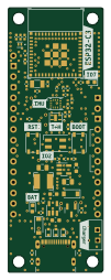 ESP32
Esp rust board
esp-rs
22.9 × 63.5 mm48 parts2LNo license648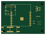 ESP32
Pcb designer ai agent
assalas
40 × 30 mm17 parts2LMIT127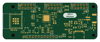 ESP32
ICE-V-Wireless
ICE-V-Wireless
81.7 × 31.8 mm78 parts4LMIT82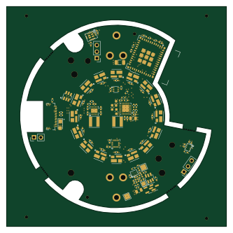 ESP32
Blinkekatze
TobleMiner
83 × 83 mm106 parts4LNo license34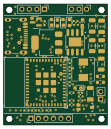 ESP32
FunHomeSwitch
ZhiFun
27.5 × 32 mm42 parts2LMIT29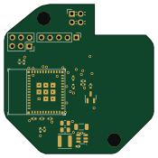 ESP32
Esp32-recirc pump controller
pdw-mb
43.6 × 43.6 mm32 parts2LNo license17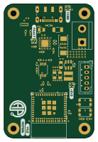 ESP32
Paperflux
albanpetit
33.5 × 50 mm43 parts4LNo license16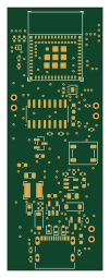 ESP32
Crimpdeq
crimpdeq
23 × 63.8 mm46 parts2LCustom license9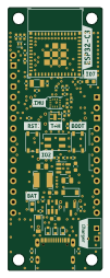 ESP32
ESP32-C3-DevKit-RUST-1
swayerloren
22.9 × 63.5 mm48 parts2LMIT8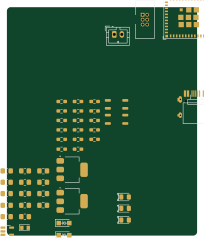 ESP32
ESP32-H2-MINI-1
74th
50.3 × 60.4 mm46 parts2LMIT8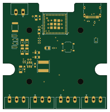 ESP32
Esptemp8c
gcormier
56.6 × 57.7 mm38 parts2LNo license8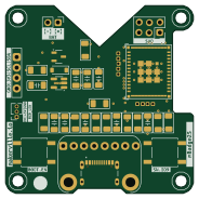 ESP32
Mbadge25
Makerville
46 × 46 mm33 parts2LCERN-OHL-P-2.06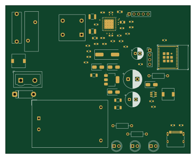 ESP32
Plc board
denorath-sys
100 × 80 mm62 parts4LCERN-OHL-W-2.05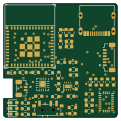 ESP32
SlimeVR-Tracker-HW
xuan25
30 × 30 mm45 parts2LMIT5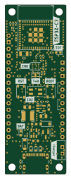 ESP32
ESP32-C3-DevKit-RUST-1
xutianq999
22.9 × 63.5 mm48 parts2LCERN-OHL-P-2.04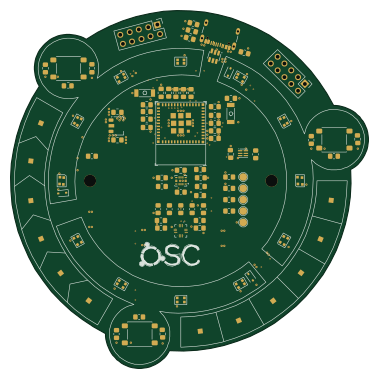 ESP32
OSCD Demo
tmjnijssen
94.6 × 94.6 mm76 parts4LCERN-OHL-P-2.03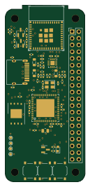 ESP32
Network player
naguirre
30.1 × 66.6 mm72 parts4LMIT3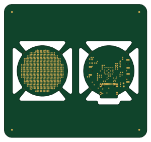 ESP32
RGB-LED-Pendant
mjhaahr
75 × 70 mm235 parts4LMIT2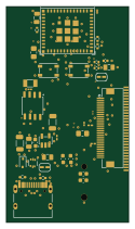 ESP32
Grupparbete-IoT25S
rt-rtos
30 × 52.7 mm41 parts4LNo license2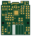 ESP32
CAN-Expansioncard
hoellwerth
26 × 30 mm38 parts4LMIT2- schematic only · 5 partsESP32
Schem
Raf3-Tech
5 partsNo license2 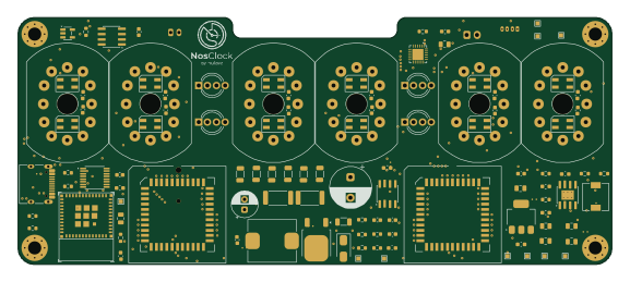 ESP32
NosClock
hulakov
144 × 60 mm103 parts2LNo license1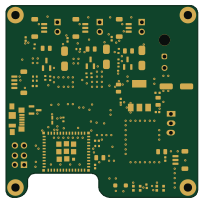 ESP32
Cloud dripper
AlessioMorale
50.8 × 50.8 mm59 parts2LMIT1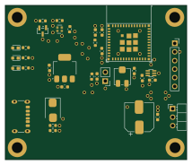 ESP32
Wirelight
kimtore
53.5 × 45.5 mm34 parts2LMIT1 ESP32
Calipers
mirdej
21.3 × 28.1 mm32 parts2LNo license1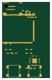 ESP32
Imu midi controller
fouiorqwe
25 × 40 mm19 parts2LMIT1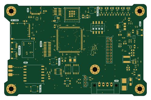 ESP32
Telem3
5aji
124 × 80 mm151 parts4LNo license0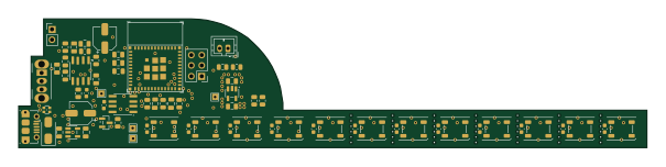 ESP32
Rainbow music pegasus
adamm
151 × 31 mm96 parts2LApache-2.00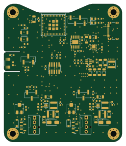 ESP32
Fan32-hardware
PfannenHans
63.5 × 74 mm96 parts4LCERN-OHL-P-2.00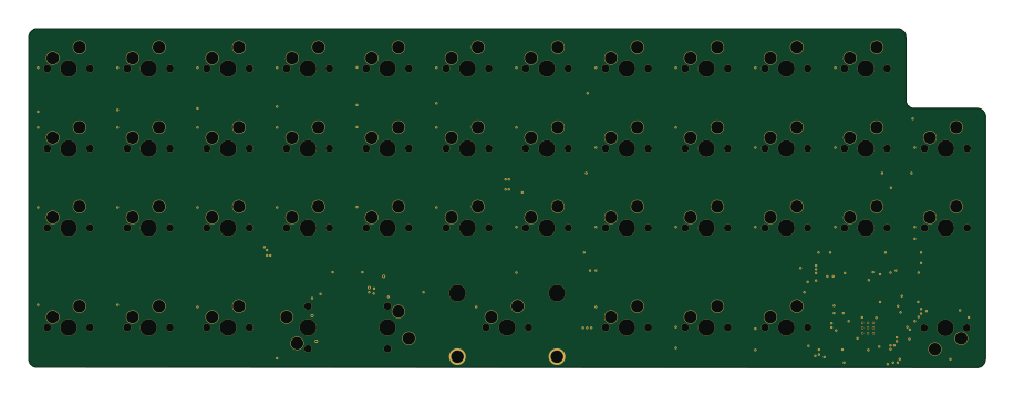 RP2040/RP2350
Pcb
sky2park
228.6 × 81 mm89 parts2LGPL-3.00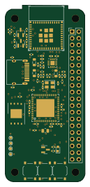 ESP32
Network player
30.1 × 66.6 mm72 parts4LNo license0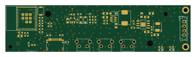 ESP32
Cereyan
fahreddinaykut
100 × 25 mm64 parts2LNo license0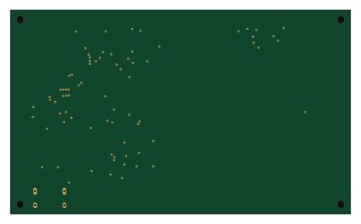 ESP32
Digital-B-Card
AhmedMKAlzoubi
100 × 60 mm62 parts2LNo license0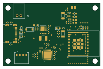 ESP32
ESP32-C3-DevKit-RUST-1
florentdenis
50.8 × 33 mm58 parts2LCustom license0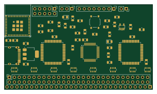 ESP32
Fence esp32
floitsch
76.2 × 44 mm57 parts2LMIT0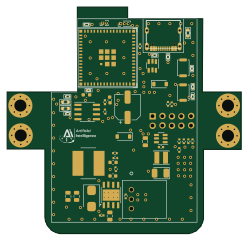 ESP32
Tiago robotiq adapter
hardware-designs-iai
62 × 60 mm56 parts4LNo license0
How designs wire the ESP32-C3-MINI-1
Read from the KiCad layouts of 53 open source designs, one per repository: what each pin of the ESP32-C3-MINI-1 connects to, and the resistors, capacitors and other passives placed on it.
- The EN/CHIP_PU pin has a pull-up to 3.3V on 44 of 50 designs, most often 10 kΩ (then 100 kΩ).
- The 3V3 pin is tied to 3.3V on 48 of 53 designs (a signal on 5).
- The EN/CHIP_PU pin has a capacitor to GND on 37 of 50 designs, most often 1 µF (then 100 nF).
- The GPIO8 pin has a pull-up to 3.3V on 33 of 48 designs, most often 10 kΩ (then 4.7 kΩ).
| Pin | Connected to | Parts on the pin |
|---|---|---|
| GNDpin 1, 2, 11, 14, 36, 37, 38, 39, 40, 41, 42, 43, 44, 45, 46, 47, 48, 49, 50, 51, 52, 53 | Connected to: GND 90% | — |
| 3V3pin 3 | Connected to: 3.3V 91% | — |
| NCpin 4, 7, 9, 10, 15, 17, 24, 25, 28, 29, 32, 33, 34, 35 | Connected to: Not connected 96% | — |
| GPIO2/ADC1_CH2pin 5 | Connected to: Signal 77% · not connected 19% |
|
| EN/CHIP_PUpin 8 | Connected to: A connector 22% |
|
| GPIO8pin 22 | Connected to: Signal 79% · not connected 21% |
|
| GPIO9pin 23 | Connected to: A connector 25% |
|
| GPIO18/USB_D-pin 26 | Connected to: A connector 49% |
|
11 more pins vary from design to design. Connections count pins, parts count designs; values in brackets are how many parts had that value. Designs read include Esp rust board by esp-rs, Pcb designer ai agent by assalas, ICE-V-Wireless by ICE-V-Wireless and Blinkekatze by TobleMiner.
The ESP32-C3-MINI-1 in open source designs
The gallery holds 86 open source boards using the ESP32-C3-MINI-1 from 58 GitHub repositories; a typical one measures about 51.8 × 49 mm and carries around 35 components.
77% are two-layer designs, the rest use four layers or more, and 58% carry an open source license.
The most starred is Esp rust board by esp-rs.
Parts used alongside the ESP32-C3-MINI-1
Microcontrollers on boards using the ESP32-C3-MINI-1
What boards using the ESP32-C3-MINI-1 are built for
ESP32-C3-MINI-1: common questions
Where can I find a ESP32-C3-MINI-1 reference design?
Each of the 86 boards on this page is a real design using the ESP32-C3-MINI-1. Open one to see how it is wired up, with the full BOM, a render of the layout and links to its KiCad files.
What pull-up resistor is used on the ESP32-C3-MINI-1 EN/CHIP_PU pin?
The EN/CHIP_PU pin has a pull-up to 3.3V on 44 of 50 designs, most often 10 kΩ (then 100 kΩ). Counted from the KiCad layouts of 53 open source designs using the ESP32-C3-MINI-1.
How is the ESP32-C3-MINI-1 3V3 pin connected?
The 3V3 pin is tied to 3.3V on 48 of 53 designs (a signal on 5). Counted from the KiCad layouts of 53 open source designs using the ESP32-C3-MINI-1.
What pull-up resistor is used on the ESP32-C3-MINI-1 GPIO8 pin?
The GPIO8 pin has a pull-up to 3.3V on 33 of 48 designs, most often 10 kΩ (then 4.7 kΩ). Counted from the KiCad layouts of 53 open source designs using the ESP32-C3-MINI-1.
What parts are used alongside the ESP32-C3-MINI-1?
The AP2112K-3.3, AMS1117-3.3, USBLC6-2SC6, MCP73831-2-OT and BME280 appear in the most repositories here.
Which microcontrollers do boards using the ESP32-C3-MINI-1 use?
Most are built on ESP32 (85) and RP2040/RP2350 (1).
How big is a typical board using the ESP32-C3-MINI-1?
The median is 51.8 × 49 mm, and 77% are two-layer designs.
What is the most popular open source board using the ESP32-C3-MINI-1?
By GitHub stars, Esp rust board by esp-rs, with 648 stars.
Can I simulate one of these boards using the ESP32-C3-MINI-1 before building it?
Yes. HardLabs turns a board's netlist and BOM into a working simulation, so you can boot and test firmware against it with no hardware on your desk.