
PowerTimer

About the PowerTimer PCB
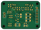
PowerTimer is an open source PCB design by jfm92, published on GitHub. It is a 2-layer board measuring 35.4 × 25.6 mm, with 28 components from 14 distinct parts.
Other key parts include the RV-3028-C7 32.768KHZ 1PPM TA QC. By type, the board carries 12 resistors, 5 transistors, 3 diodes, 3 capacitors, 2 connectors and 1 IC.
It belongs with the power & battery and sensors designs in this gallery.
From the project
Module to jump from miliAmperes to nanoAmperes on Idle mode.
The Power Timer is an ultra-low power module that allows you to control the output power by software. It is mainly based on a Real-Time Clock (RTC) and an RS circuit. Thanks to the RTC, you can control the exact wake-up date or the periodicity. It also allows for external interruptions, which gives you the benefits of ultra-low power consumption while being able to connect other types of sensors. The module is based on the RV3028-C7 chip. It is also compatible with Arduino, thanks to its custom library.
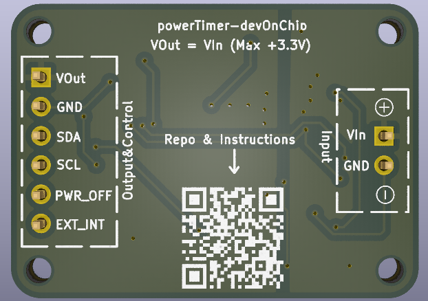
Main components on the PowerTimer
PowerTimer bill of materials (BOM)
28 components, 14 distinct parts.
| Qty | Part | Footprint | Refs |
|---|---|---|---|
| 1 | RV-3028-C7 32.768KHZ 1PPM TA QC | OSC-SMD_8P-L3.2-W1.5-P0.90-BL | U1 |
| 3 | AO3401A | SOT-23 | Q1, Q4, Q5 |
| 2 | S8050H | SOT-23-3_L2.9-W1.6-P1.90-LS2.8-BR | Q2, Q3 |
| 1 | Conn_01x02 | PinHeader_1x02_P2.54mm_Vertical | J1 |
| 1 | Conn_01x06 | PinHeader_1x06_P2.54mm_Vertical | J2 |
| 1 | TS-1185EC-C-D-B | SW-SMD_4P-L3.7-W3.0-P1.50-LS4.7 | SW1 |
| 1 | 0805G (Green) | LED0805-R-RD | LED1 |
| 3 | LL4148 | D_MiniMELF | D1, D2, D3 |
| 1 | 100nF | C_0603_1608Metric_Pad1.08x0.95mm_HandSolder | C1 |
| 1 | 10uF | C_0603_1608Metric_Pad1.08x0.95mm_HandSolder | C2 |
| 1 | TAJA475K016RNJ | CASE-A_3216 | C3 |
| 7 | 10K | R_0603_1608Metric_Pad0.98x0.95mm_HandSolder | R1, R3, R5, R6, R10, R11, R14 |
| 4 | 100K | R_0603_1608Metric_Pad0.98x0.95mm_HandSolder | R2, R4, R7, R8 |
| 1 | 470 | R_0603_1608Metric_Pad0.98x0.95mm_HandSolder | R9 |
PowerTimer design files
The KiCad project lives in the jfm92/powerTimer repository on GitHub; these links point at the commit this page was built from.
PowerTimer: common questions
How big is the PowerTimer PCB?
The PowerTimer measures 35.4 × 25.6 mm, has 2 copper layers and is 1.6 mm thick.
How many components are on the PowerTimer?
28 components, from 14 distinct parts. The full bill of materials is listed on this page.
Where can I download the PowerTimer design files?
From the jfm92/powerTimer repository on GitHub, which has the KiCad layout and the schematic; the links under Design files point to each one.
Can I use the PowerTimer design in my own project?
The repository has no license, so all rights stay with jfm92. Use it as a reference, and ask the author before reusing the design.
Similar boards

Sensor smd
scottbez1
40 × 20 mm5 parts2LApache-2.04.2k
Sensors
StuckAtPrototype
15.2 × 9 mm14 parts4LApache-2.03.8k
Stack chan
stack-chan
50 × 50 mm33 parts2LApache-2.01.7k
Display Carrier
AxxAxx
35.6 × 58.2 mm5 parts2LGPL-3.01.7k
Microphone
Mentra-Community
5.5 × 6.1 mm6 parts2LMIT1.2k
TemperaturePCB PANEL
stuartpittaway
116 × 75.5 mm178 parts2LCC-BY-NC-4.01.1k