
BMP-REDFit adapter


About the BMP-REDFit adapter PCB
BMP-REDFit adapter is an open source PCB design by JitterCompany, published on GitHub under the MIT license. It is a 2-layer board measuring 22.9 × 16.5 mm, with 4 components from 4 distinct parts.
From the project
Collection of useful utility PCBs for development purposes
Adapter PCB to connect a 6 pins REDFIT IDF SKEDD connector
Part | Manufacturer | Order Code | URL ---|---|---|--- Pre-Pressed Cable | Wurth | 490107670612S | we-online.com Pre-assembled microfit cable | Molex | 15134-0403 | mouser.com
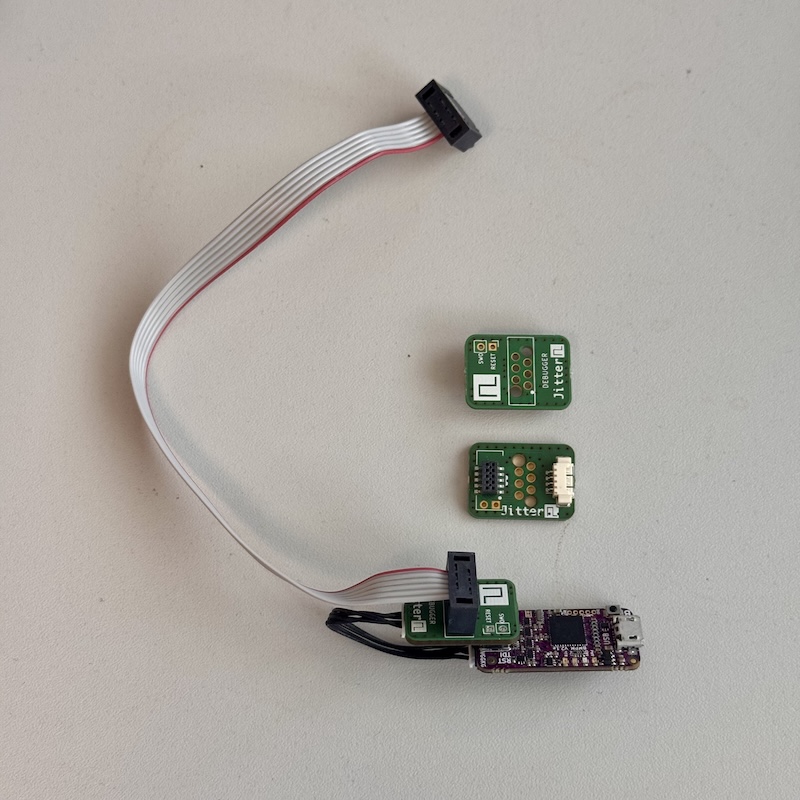
BMP-REDFit adapter bill of materials (BOM)
4 components, 4 distinct parts.
| Qty | Part | Footprint | Refs |
|---|---|---|---|
| 1 | FLE-105-01-G-DV Conn_ARM_JTAG_SWD_10 Samtec | connector_jtag_10pin-female-mirrored | J1 |
| 1 | 53261-0471 UART_ClientSide Molex | Molex_PicoBlade_53261-0471_1x04-1MP_P1.25mm_Horizontal | J2 |
| 1 | Jitter_Debug_HostSide | WR-WST_REDFIT-6-pins_490107670612-adapter_to_pcb | J3 |
| 1 | Conn_01x02_Pin | PinHeader_1x02_P2.54mm_Vertical | J4 |
BMP-REDFit adapter design files
The KiCad project lives in the JitterCompany/debug-tools repository on GitHub; these links point at the commit this page was built from.
BMP-REDFit adapter: common questions
How big is the BMP-REDFit adapter PCB?
The BMP-REDFit adapter measures 22.9 × 16.5 mm, has 2 copper layers and is 1.6 mm thick.
How many components are on the BMP-REDFit adapter?
4 components, from 4 distinct parts. The full bill of materials is listed on this page.
Where can I download the BMP-REDFit adapter design files?
From the JitterCompany/debug-tools repository on GitHub, which has the KiCad layout and the schematic; the links under Design files point to each one.
Can I use the BMP-REDFit adapter design in my own project?
Yes, under the terms of its MIT license, which JitterCompany chose for the repository.
More boards in debug-tools
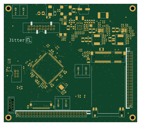 STM32
SL23 modem tester
120 × 107 mm195 parts4LMIT0
USBSwitch
41 × 40 mm13 parts2LMIT0
JLink-REDfit adapter
27.4 × 26 mm5 parts2LMIT0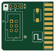
Jlink to TC2030-IDC microchip adapter
27.4 × 26 mm5 parts2LMIT0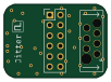
HSprobe-REDFit adapter
25 × 18 mm3 parts2LMIT0
JTAG-SWD
16.5 × 12.7 mm3 parts2LMIT0