
SL23 modem tester

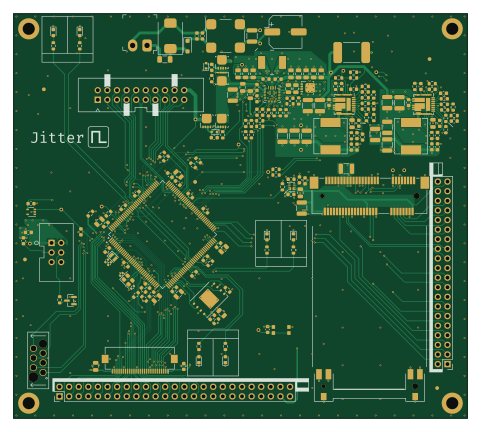
About the SL23 modem tester PCB
SL23 modem tester is an open source STM32 PCB design by JitterCompany, published on GitHub under the MIT license. It is a 4-layer board measuring 120 × 107 mm, with 195 components from 67 distinct parts.
Its main chip is the STM32L4R7ZIT6, from the STM32 family. Other key parts include the BQ25672RQMR, SIC473ED-T1-GE3, SLG59M301V, W25Q256JVEIQ and MCP9701AT-E/LT. By type, the board carries 97 capacitors, 57 resistors, 10 diodes, 8 connectors, 7 ICs and 6 transistors.
From the project
Collection of useful utility PCBs for development purposes
A test jig for the modules that plug into a Sensor Link host board. It carries a mini-PCIe slot for an LTE module, an SL23 extension FFC, and a UI-board connector, and it ships with factory-test firmware that gives a pass/fail verdict on LEDs plus a machine-readable log over RTT.
The board is a stripped-down Sensor Link host: same MCU (STM32L4R7), same pinout for everything a module touches, with the external SRAM and several unrelated parts left off. That compatibility is deliberate — the test firmware can be proven on a real host board before any jig exists, and the jig can run ordinary…
Main components on the SL23 modem tester
SL23 modem tester bill of materials (BOM)
195 components, 67 distinct parts.
| Qty | Part | Footprint | Refs |
|---|---|---|---|
| 1 | BQ25672RQMR BQ25672 | TI_VQFN-HR-29-RQM | U1 |
| 2 | SIC473ED-T1-GE3 | Vishay_MLP55-27L | U2, U3 |
| 1 | STM32L4R7ZIT6 STM32L4R7ZITx | LQFP-144_20x20mm_P0.5mm | U5 |
| 1 | SLG59M301V | DFN200X150X80-8N | U6 |
| 1 | W25Q256JVEIQ | WSON-8-1EP_8x6mm_P1.27mm_EP3.4x4.3mm | U8 |
| 1 | MCP9701AT-E/LT MCP9701A | SOT-353_SC-70-5 | U11 |
| 5 | CSD17581Q3A | CSD17552Q3A | Q1, Q2, Q3, Q4, Q5 |
| 1 | BSS138BK,215 | SOT-23 | Q7 |
| 1 | ABM10-167-12.000MHZ-T3 12 MHz | Crystal_SMD_2520-4Pin_2.5x2.0mm | Y1 |
| 1 | ABS06-32.768KHZ-9-1-T 32.768kHz | Crystal_SMD_ABS06-2Pin_2.0x1.2mm | Y2 |
| 1 | 691322310002 | TerminalBlock_Wurth_WR-TBL_691322310002_1x02_P3.81mm_Horizontal | J1 |
| 1 | MM60-EZH039-B5-R850 | MM60-EZH039-B5-R850 | J2 |
| 1 | 68602-450HLF | PinHeader_2x25_P2.54mm_Vertical | J4 |
| 1 | ~ | PinHeader_2x20_P2.54mm_Vertical | J6 |
| 1 | MM60-52B1-G1-R850 | BUS_PCI_Express_Mini_MM60-52B1-G1-R850 | J7 |
| 1 | FH12-30S-0.5SH(55) Conn_01x30 | Hirose_FH12-30S-0.5SH_1x15-1MP_P0.50mm_Horizontal | J10 |
| 1 | 30320-6002HB | IDC_Header_2x10_P2.54mm_Vertical_MALE | J12 |
| 1 | 61200621621 | IDC_Header_2x03_P2.54mm_Vertical_Male | J13 |
| 1 | CC12H3.5A-TR 3.5A | Fuse_1206_3216Metric | F1 |
| 1 | 2920L100 1.1A | Fuse_2920 | F2 |
Show 47 more
| Qty | Part | Footprint | Refs |
|---|---|---|---|
| 1 | KMR731NG LFS SW_Push | C&K_KMR7_button | SW2 |
| 1 | PMEG40T30ER | D_SOD-123F | D1 |
| 1 | XMC7K24CA-M3/H 24V | D_SMC | D2 |
| 2 | BZT52C12T-7 12V | D_SOD-523 | D3, D4 |
| 3 | 150060RS75000 Red, 625 nm | LED_0603_1608Metric | D5, D7, D10 |
| 3 | 150060VS75000 Green, 570 nm | LED_0603_1608Metric | D6, D8, D11 |
| 1 | 74279261 80 | L_0603_1608Metric | FB2 |
| 1 | 744273801 | L_CommonModeChoke_Wuerth_WE-SL5-HC | L1 |
| 1 | SPM6530T-1R0M120 1u | L_TDK_SPM6530 | L2 |
| 2 | 74437358082 8.2uH | L_Wuerth_LHMI_8040 | L3, L4 |
| 5 | CGA3E1X7R1V105K080AC 1u | C_0603_1608Metric | C1, C30, C45, C51, C106 |
| 6 | CL32A106KBJNNNE 10u | C_1210_3225Metric | C2, C27, C28, C42, C43, C79 |
| 1 | 865080553013 150u | CP_Elec_8x10.5_wurth_WCAP_ASLI | C3 |
| 4 | CGA3E2X7R1H102K080AA 1n | C_0603_1608Metric | C4, C5, C37, C58 |
| 34 | CGA3E2X7R1H104K080AA 0.1u | C_0603_1608Metric | C7, C12, C13, C14, C15, C20, C32, C35 +26 |
| 12 | GRM21BR61H106KE43L 10u | C_0805_2012Metric | C8, C9, C10, C11, C19, C21, C22, C23 +4 |
| 4 | GRM21BZ71H475KE15K 4u7 | C_0805_2012Metric | C16, C29, C44, C94 |
| 2 | CGA3E2X7R1H473K080AA 47n | C_0603_1608Metric | C17, C18 |
| 4 | CGA3E3X7R1H224K080AB 220n | C_0603_1608Metric | C31, C33, C46, C48 |
| 2 | GCM188L81H561KA03D 560p | C_0603_1608Metric | C34, C74 |
| 2 | CGA3E2C0G1H272J080AE 2n7 | C_0603_1608Metric | C36, C78 |
| 5 | CL32A107MQVNNNE 100u | C_1210_3225Metric | C39, C54, C55, C93, C95 |
| 2 | DNP | C_1210_3225Metric | C40, C41 |
| 1 | GCM1885C1H681JA16J 680p | C_0603_1608Metric | C49 |
| 2 | CGA3E2X7R1H472M080AA 4n7 | C_0603_1608Metric | C52, C92 |
| 1 | C3225X5R1A476M250AC 47u | C_1210_3225Metric | C56 |
| 6 | 10u | C_0805_2012Metric | C65, C67, C70, C75, C82, C99 |
| 2 | CGA2B2NP01H060D050BA 6p | C_0402_1005Metric | C111, C112 |
| 2 | GCM1555C1H130JA16D 13p | C_0402_1005Metric | C113, C114 |
| 5 | 48.7k | R_0603_1608Metric | R1, R8, R21, R37, R51 |
| 15 | CRCW060310K0FKEAHP 10k | R_0603_1608Metric | R2, R15, R16, R20, R26, R27, R31, R32 +7 |
| 2 | CRCW0603294RFKEA 294 | R_0603_1608Metric | R3, R4 |
| 5 | 4.12k | R_0603_1608Metric | R7, R10, R13, R19, R36 |
| 1 | 120k | R_0603_1608Metric | R9 |
| 3 | CRCW06036K04FKEAC 6.04k | R_0603_1608Metric | R11, R25, R41 |
| 6 | CRCW0603100RFKEAC 100 Vishay | R_0603_1608Metric | R12, R18, R43, R44, R46, R52 |
| 1 | CRCW060315K4FKEB 15.4k | R_0603_1608Metric | R14 |
| 3 | CRCW0603374RFKEA 374 Vishay | R_0603_1608Metric | R17, R40, R54 |
| 2 | CRCW0603120KFKEAC 120k | R_0603_1608Metric | R22, R33 |
| 1 | CR0603-FX-2673ELF 267k | R_0603_1608Metric | R23 |
| 2 | CRCW06032R20FKEAC 2.2 | R_0603_1608Metric | R24, R35 |
| 2 | DNP | R_0603_1608Metric | R28, R50 |
| 2 | 10k | R_0603_1608Metric | R29, R53 |
| 1 | DNI | R_0603_1608Metric | R30 |
| 2 | CRCW0603348KFKEA 348K | R_0603_1608Metric | R34, R56 |
| 2 | 15.4k | R_0603_1608Metric | R38, R55 |
| 2 | 2.2 | R_0603_1608Metric | R47, R65 |
SL23 modem tester design files
The KiCad project lives in the JitterCompany/debug-tools repository on GitHub; these links point at the commit this page was built from.
SL23 modem tester: common questions
What microcontroller does the SL23 modem tester use?
The SL23 modem tester is built around the STM32L4R7ZIT6, from the STM32 family.
How big is the SL23 modem tester PCB?
The SL23 modem tester measures 120 × 107 mm, has 4 copper layers and is 1.6 mm thick.
How many components are on the SL23 modem tester?
195 components, from 67 distinct parts. The full bill of materials is listed on this page.
Where can I download the SL23 modem tester design files?
From the JitterCompany/debug-tools repository on GitHub, which has the KiCad layout and the schematic; the links under Design files point to each one.
Can I use the SL23 modem tester design in my own project?
Yes, under the terms of its MIT license, which JitterCompany chose for the repository.
Can I test firmware for the SL23 modem tester without the hardware?
Yes. HardLabs builds a simulation of the board from its netlist and BOM, so you can run and debug STM32 firmware against it before you order a PCB.
More boards in debug-tools
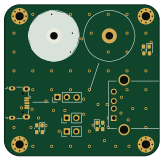
USBSwitch
41 × 40 mm13 parts2LMIT0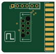
JLink-REDfit adapter
27.4 × 26 mm5 parts2LMIT0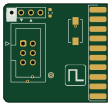
Jlink to TC2030-IDC microchip adapter
27.4 × 26 mm5 parts2LMIT0
BMP-REDFit adapter
22.9 × 16.5 mm4 parts2LMIT0
HSprobe-REDFit adapter
25 × 18 mm3 parts2LMIT0
JTAG-SWD
16.5 × 12.7 mm3 parts2LMIT0
Similar boards
 STM32
LumenPnP Motherboard
opulo-inc
149 × 95 mm296 parts4LCC-BY-SA-4.03.7k STM32
Type g
google
169 × 30 mm24 parts2LApache-2.02.9k STM32
Main panel
234 × 84 mm26 parts4LApache-2.02.9k STM32
Base
52.3 × 52.3 mm36 parts2LApache-2.02.9k STM32
Type a
150 × 30 mm14 parts2LApache-2.02.9k STM32
Type c
188 × 30 mm17 parts2LApache-2.02.9k