
ADC and amplifier pico breakout board

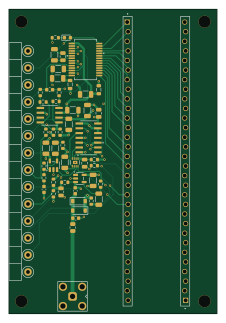
About the ADC and amplifier pico breakout board
ADC and amplifier pico breakout board is an open source RP2040/RP2350 PCB design by Jolt8, published on GitHub. It is a 4-layer board measuring 55 × 80.5 mm, with 66 components from 41 distinct parts.
Its main chip is the Pimoroni_Pico_LiPo_2_XL_W, from the RP2040/RP2350 family. Other key parts include the MAX5394LATA+T, 74AHCT125D_118, OPA365XXDBV, AD9226ARSRL and AD8138AR-REEL. By type, the board carries 20 capacitors, 19 resistors, 14 test points, 6 ICs, 3 diodes and 2 connectors.
It belongs with the audio and dev boards & breakouts designs in this gallery.
From the project
This is a repo for all the pieces of code I've written while learning chemical engineering.
This is a repo for all the pieces of code I've written while learning chemical engineering.
Many of my python projects are quite old as I have switched to Julia.
The only thing I haven't ported to Julia from python is my old and incomplete process simulator and my MESH distillation solver.
Most of the work I've done recently has revolved around solving ODEs, PDEs in Julia as well as working ModelingToolkit.jl
Main components on the ADC and amplifier pico breakout board
ADC and amplifier pico breakout board bill of materials (BOM)
66 components, 41 distinct parts — part numbers from the project's BOM.
| Qty | Part | Footprint | Refs |
|---|---|---|---|
| 1 | MAX5394LATA+T | 21-0168_T822-2_MXM | U1 |
| 1 | 74AHCT125D_118 SN74AHCT125DRG4 | D14_TEX | U2 |
| 2 | OPA365XXDBV OPA365xxDBV | SOT-23-5 | U3, U4 |
| 1 | AD9226ARSRL | RS_28_ADI | U5 |
| 1 | AD8138AR-REEL | R_8_ADI | U6 |
| 1 | SMA_KWE_THT | SMA_KWE | J1 |
| 1 | Pimoroni_Pico_LiPo_2_XL_W | Pimoroni Pico LiPo 2 XL W (Staggered pins) | J2 |
| 1 | SPI_CS | TestPoint_Loop_D2.50mm_Drill1.0mm | TP1 |
| 1 | AMP1_OUT | TestPoint_Loop_D2.50mm_Drill1.0mm | TP2 |
| 1 | AMP2_IN | TestPoint_Loop_D2.50mm_Drill1.0mm | TP3 |
| 1 | AMP2_OUT | TestPoint_Loop_D2.50mm_Drill1.0mm | TP4 |
| 1 | TP_GND1 | TestPoint_Loop_D2.50mm_Drill1.0mm | TP5 |
| 1 | TP_GND2 | TestPoint_Loop_D2.50mm_Drill1.0mm | TP6 |
| 1 | 5VA | TestPoint_Loop_D2.50mm_Drill1.0mm | TP7 |
| 1 | DIGIPOT_2.5V | TestPoint_Loop_D2.50mm_Drill1.0mm | TP8 |
| 1 | SIG_2.5V | TestPoint_Loop_D2.50mm_Drill1.0mm | TP9 |
| 1 | ADC OTR | TestPoint_Loop_D2.50mm_Drill1.0mm | TP10 |
| 1 | ADC 2.5V | TestPoint_Loop_D2.50mm_Drill1.0mm | TP11 |
| 1 | ADC VREF | TestPoint_Loop_D2.50mm_Drill1.0mm | TP12 |
| 1 | ADC_CLK | TestPoint_Loop_D2.50mm_Drill1.0mm | TP13 |
Show 21 more
| Qty | Part | Footprint | Refs |
|---|---|---|---|
| 1 | SIG_FILTERED | TestPoint_Loop_D2.50mm_Drill1.0mm | TP14 |
| 2 | 1N4148W | D_SOD-123 | D1, D2 |
| 1 | LED | LED_0603_1608Metric | D3 |
| 2 | FerriteBead | L_0805_2012Metric | FB1, FB2 |
| 5 | 0.1UF 100nF | C_1206_3216Metric | C1, C2, C11, C14, C15 |
| 1 | 2.7NF 2.7nF | C_0603_1608Metric | C3 |
| 1 | 1NF 1nF | C_0603_1608Metric | C4 |
| 3 | 100NF 100nF | C_1206_3216Metric | C5, C8, C9 |
| 2 | 330NF 330nF | C_1206_3216Metric | C6, C7 |
| 4 | 10UF 10uF | C_0805_2012Metric | C10, C12, C17, C18 |
| 1 | 820PF 820pF | C_0603_1608Metric | C13 |
| 1 | 47PF 47pF | C_0603_1608Metric | C16 |
| 2 | 100nF | C_1206_3216Metric | C19, C20 |
| 1 | 1k | R_0805_2012Metric | R1 |
| 1 | 100K 100k | R_0603_1608Metric | R2 |
| 1 | 50 | R_0603_1608Metric | R3 |
| 5 | 1k | R_0603_1608Metric | R4, R8, R9, R14, R20 |
| 3 | 499 | R_0603_1608Metric | R5, R16, R17 |
| 2 | 9k | R_0603_1608Metric | R6, R7 |
| 4 | 10K 10k | R_0603_1608Metric | R10, R11, R12, R13 |
| 2 | 33 | R_0603_1608Metric | R18, R19 |
ADC and amplifier pico breakout board design files
The KiCad project lives in the Jolt8/Projects-And-Code-Will-Martin repository on GitHub; these links point at the commit this page was built from.
ADC and amplifier pico breakout board: common questions
What microcontroller does the ADC and amplifier pico breakout board use?
The ADC and amplifier pico breakout board is built around the Pimoroni_Pico_LiPo_2_XL_W, from the RP2040/RP2350 family.
How big is the ADC and amplifier pico breakout board?
The ADC and amplifier pico breakout board measures 55 × 80.5 mm, has 4 copper layers and is 1.6 mm thick.
How many components are on the ADC and amplifier pico breakout board?
66 components, from 41 distinct parts, with part numbers taken from the project's own BOM. The full bill of materials is listed on this page.
Where can I download the ADC and amplifier pico breakout board design files?
From the Jolt8/Projects-And-Code-Will-Martin repository on GitHub, which has the KiCad layout, the schematic and the BOM; the links under Design files point to each one.
Can I use the ADC and amplifier pico breakout board design in my own project?
The repository has no license, so all rights stay with Jolt8. Use it as a reference, and ask the author before reusing the design.
Can I test firmware for the ADC and amplifier pico breakout board without the hardware?
Yes. HardLabs builds a simulation of the board from its netlist and BOM, so you can run and debug RP2040/RP2350 firmware against it before you order a PCB.
More boards in Projects-And-Code-Will-Martin
Similar boards
 RP2040/RP2350
Open Book Abridged Edition
joeycastillo
85 × 115 mm29 parts2LCC-BY-SA-4.08.1k RP2040/RP2350
Corne
foostan
277.2 × 107.5 mm164 parts2LCC-BY-4.07.7k RP2040/RP2350
Corne
277.2 × 107.5 mm164 parts2LCC-BY-4.07.7k RP2040/RP2350
LogicAnalyzer
gusmanb
57 × 55.2 mm6 parts2LGPL-3.05.0k RP2040/RP2350
Jitx design
55.5 × 65 mm26 parts4LGPL-3.05.0k RP2040/RP2350
Pro V2
kata0510
290.1 × 130 mm270 parts2LMIT2.3k