
Motor high current sensors

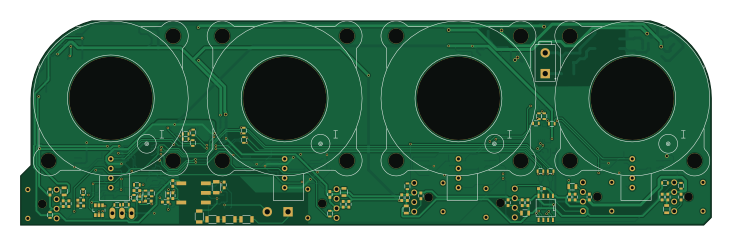
About the Motor high current sensors PCB
Motor high current sensors is an open source NXP PCB design by jonblissett, published on GitHub under the GPL-3.0 license. It is a 2-layer board measuring 182.8 × 54 mm, with 221 components from 51 distinct parts.
Its main chip is the ADCMP671, from the NXP family. Other key parts include the Murata_MTU1, LTC1407-1, LTC1407, LD1117S33TR and MCP1700T-330. By type, the board carries 108 capacitors, 56 resistors, 20 ICs, 13 inductors, 2 connectors and 2 diodes.
It belongs with the sensors designs in this gallery.
From the project
Design for a quadruple current sensing board using the LEM HTFS series current sensors, for 200-800A providing 14-bit digital outputs with optical signalling. Designed for sensing 3-phase and DC-bus current on electric vehicles and tested on a racing electric motorcycle.
Main components on the Motor high current sensors
Motor high current sensors bill of materials (BOM)
221 components, 51 distinct parts.
| Qty | Part | Footprint | Refs |
|---|---|---|---|
| 2 | Murata_MTU1 | MTU1_Murata_DCDC | IC1, IC2 |
| 2 | LTC1407-1 | MSOP-10-1EP_3x3mm_Pitch0.5mm | U1, U2 |
| 1 | LTC1407 | MSOP-10-1EP_3x3mm_Pitch0.5mm | U3 |
| 1 | LD1117S33TR | SOT-223 | U4 |
| 1 | MCP1700T-330 | SOT-23 | U5 |
| 2 | MC78M05CDT | TO-252-2Lead | U6, U18 |
| 1 | MCP1700T-500 | SOT-23 | U7 |
| 3 | HTFS800 | HTFS-Series_LEM-HallEffektCurrentTransducer | U8, U9, U10 |
| 1 | HTFS400 | HTFS-Series_LEM-HallEffektCurrentTransducer | U11 |
| 1 | ACPL-C870 | DIP-8_SMD | U12 |
| 4 | MAX7480 | SOIC-8_3.9x4.9mm_Pitch1.27mm | U13, U14, U15, U16 |
| 1 | OPA350 | SOIC-8_3.9x4.9mm_Pitch1.27mm | U17 |
| 2 | CONN_01X02 | Connector_Header_2Way_39-29-3026 | P1, P2 |
| 4 | NFE61P | EMI_Filter_murata | FI1, FI2, FI3, FI4 |
| 3 | DS90LV028A | SOIC-8-N | I1, I2, I3 |
| 1 | DS90LV027A | SOIC-8-N | I4 |
| 5 | ADCMP671 | TSOT-6-MK06A | I5, I6, I7, I8, I9 |
| 4 | AFBR-1634Z | HFBR-xx3xZ | OPT1, OPT2, OPT3, OPT6 |
| 2 | AFBR-26x | HFBR-xx3xZ | OPT4, OPT5 |
| 1 | R_PACK4 | ACAS0612 | RP1 |
Show 31 more
| Qty | Part | Footprint | Refs |
|---|---|---|---|
| 2 | 3.3V | SOD-523 | D2, D3 |
| 1 | INDUCTOR_SMALL | Neosid_Inductor_SM0603CG | L1 |
| 2 | 10uH | Neosid_Inductor_SM1206 | L2, L3 |
| 6 | 1uH | R_0805 | L4, L5, L6, L10, L11, L13 |
| 3 | ? | R_0805 | L7, L8, L9 |
| 1 | 10uH | Neosid_Inductor_SM0603CG | L12 |
| 10 | 5.1n | C_0603 | C1, C2, C3, C4, C5, C6, C98, C99 +2 |
| 18 | 10u | C_0603 | C7, C8, C9, C10, C11, C12, C20, C21 +10 |
| 1 | 22u, 16V | C_1210 | C13 |
| 28 | 100n | C_0603 | C14, C15, C16, C17, C18, C19, C28, C29 +20 |
| 7 | 1u | C_0603 | C23, C24, C25, C54, C103, C105, C107 |
| 8 | 1n | C_0603 | C26, C27, C46, C68, C69, C104, C106, C108 |
| 3 | 10u, 6.3v | C_0805 | C34, C35, C36 |
| 4 | 10n | C_0603 | C37, C38, C39, C52 |
| 4 | 4u7 | C_0805 | C40, C41, C42, C51 |
| 17 | 47n | C_0603 | C55, C56, C57, C58, C59, C60, C61, C62 +9 |
| 4 | 4n7 | C_0603 | C64, C65, C66, C67 |
| 4 | 27p | C_0603 | C70, C71, C72, C73 |
| 8 | 3.6k | R_0603 | R1, R2, R3, R4, R54, R55, R56, R57 |
| 2 | 51 | R_0603 | R5, R6 |
| 8 | 6.8k | R_0603 | R7, R8, R9, R10, R58, R59, R60, R61 |
| 4 | 4k7 | R_0603 | R11, R12, R13, R46 |
| 6 | 330 | R_0603 | R14, R15, R16, R17, R18, R19 |
| 4 | 100k | R_1206 | R20, R21, R22, R23 |
| 1 | 158 | R_0603 | R24 |
| 4 | 1k6 | R_0603 | R30, R33, R36, R39 |
| 4 | 910 | R_0603 | R31, R34, R37, R40 |
| 4 | 270 | R_0603 | R32, R35, R38, R41 |
| 9 | DNP | R_0603 | R42, R43, R44, R45, R47, R48, R49, R50 +1 |
| 1 | 0R | R_0603 | R52 |
| 1 | 270 | R_1206 | R53 |
Motor high current sensors design files
The KiCad project lives in the jonblissett/motor-high-current-sensors repository on GitHub; these links point at the commit this page was built from.
Motor high current sensors: common questions
What microcontroller does the Motor high current sensors use?
The Motor high current sensors is built around the ADCMP671, from the NXP family.
How big is the Motor high current sensors PCB?
The Motor high current sensors measures 182.8 × 54 mm, has 2 copper layers and is 1.6 mm thick.
How many components are on the Motor high current sensors?
221 components, from 51 distinct parts. The full bill of materials is listed on this page.
Where can I download the Motor high current sensors design files?
From the jonblissett/motor-high-current-sensors repository on GitHub, which has the KiCad layout; the links under Design files point to each one.
Can I use the Motor high current sensors design in my own project?
Yes, under the terms of its GPL-3.0 license, which jonblissett chose for the repository.
Can I test firmware for the Motor high current sensors without the hardware?
Yes. HardLabs builds a simulation of the board from its netlist and BOM, so you can run and debug NXP firmware against it before you order a PCB.
Similar boards
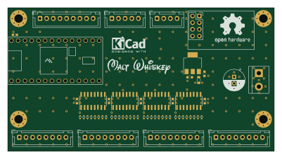 NXP
NXP32Bit shift register
MaltWhiskey
100 × 54 mm56 parts4LNo license763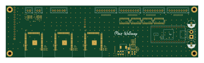 NXP
NXPMega-Cube-Board
200 × 54 mm100 parts4LNo license763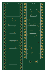 NXP
NXPMCL64
MicroCoreLabs
39.3 × 61.8 mm9 parts4LNo license532 NXP
NXPROM Emulator
21.5 × 37.1 mm5 parts2LNo license532 NXP
NXPMCLZ8
37.1 × 61.5 mm6 parts4LNo license532 NXP
NXPXTMAX
81 × 46 mm14 parts4LNo license532