
FM-radio

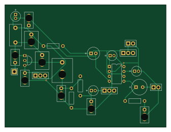
About the FM-radio PCB
FM-radio is an open source PCB design by Junquilh0, published on GitHub. It is a 2-layer board measuring 84.1 × 63.6 mm, with 28 components from 27 distinct parts.
Other key parts include the LM386. By type, the board carries 11 capacitors, 3 resistors, 1 IC, 1 transistor, 1 antenna and 1 battery holder.
It belongs with the rf & radio and audio designs in this gallery.
From the project
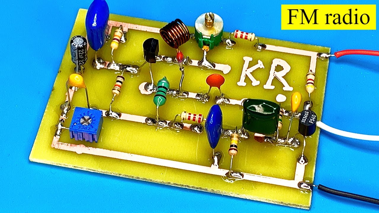
While making this I saw a lot of different designs for similar radios. Mine is made of essentially two parts: ### The receiver - The coil (L) and the small variable capacitor (Cosc) choose which frequency the radio "listens" to. The frequency the radio points to is around 100 MHz
While making this I saw a lot of different designs for similar radios. Mine is made of essentially two parts: ### The receiver - The coil (L) and the small variable capacitor (Cosc) choose which frequency the radio "listens" to. The frequency the radio points to is around 100 MHz, and changing the capacitor or slightly adjusting the coil (it's handmade) moves it across the FM band; - The antenna is a 75 cm wire because that's one fourth of the wavelength of a normal radio wave. It connects through a tiny 2 pF capacitor (C3) so it does not mess up the tuning; - The transistor (Q1) makes the…
Main components on the FM-radio
FM-radio bill of materials (BOM)
28 components, 27 distinct parts.
| Qty | Part | Footprint | Refs |
|---|---|---|---|
| 1 | LM386 | DIP-8_W7.62mm_LM386 | U1 |
| 1 | BF494 | TO-92_Inline_CEB | Q1 |
| 1 | Antenna 75cm | Wire_1x01_P2.54mm | AE1 |
| 1 | 9V | Wire_1x02_P2.54mm | BT1 |
| 1 | 10 μF | CP_Radial_D5.0mm_P2.00mm | C_bypass1 |
| 1 | 5-20pf | Trimmer_C_Slot_P2.5-5.08mm | C_oscilator1 |
| 1 | 2-10 pF | Trimmer_C_Slot_P2.5-5.08mm | C_regen1 |
| 1 | Speaker | Wire_1x02_P2.54mm | LS1 |
| 1 | 5 turns (adjustable) | L_Air_P7.62mm_Handwound | L_oscilator1 |
| 1 | 10 kΩ | R_Axial_L6.3mm_D2.5mm_P10.16mm | R_audio1 |
| 1 | SW_SPST | Wire_1x03_P2.54mm | SW1 |
| 1 | 10 μH | L_Radial_Slot_P5.0-7.5mm | XRF1 |
| 1 | 10 KΩ | Wire_1x03_P2.54mm | poten1 |
| 1 | 50 KΩ | Wire_1x03_P2.54mm | poten2 |
| 2 | 10 μF | CP_Radial_D5.0mm_P2.00mm | C1, C7 |
| 1 | 100 nF | C_Ceramic_Slot_P2.54-5.08mm | C2 |
| 1 | 2 pF | C_Ceramic_Slot_P2.54-5.08mm | C3 |
| 1 | 1,2nF | C_Ceramic_Slot_P2.54-5.08mm | C4 |
| 1 | 10 nF | C_Ceramic_Slot_P2.54-5.08mm | C5 |
| 1 | 4,7 nF | C_Ceramic_Slot_P2.54-5.08mm | C6 |
Show 7 more
| Qty | Part | Footprint | Refs |
|---|---|---|---|
| 1 | 220 μF | CP_Radial_D8.0mm_P3.50mm | C8 |
| 1 | 1 μF | CP_Radial_D5.0mm_P2.00mm | C9 |
| 1 | 47 nF | C_Ceramic_Slot_P2.54-5.08mm | C12 |
| 1 | 100 μF | CP_Radial_D6.3mm_P2.50mm | C13 |
| 1 | 1 KΩ | R_Axial_L6.3mm_D2.5mm_P10.16mm | R1 |
| 1 | 2.2 kΩ | R_Axial_L6.3mm_D2.5mm_P10.16mm | R2 |
| 1 | 10 Ω | R_Axial_L6.3mm_D2.5mm_P10.16mm | R3 |
FM-radio design files
The KiCad project lives in the Junquilh0/FM-radio repository on GitHub; these links point at the commit this page was built from.
- LayoutRadio 1/Radio 1.kicad_pcb
- SchematicRadio 1/Radio 1.kicad_sch
FM-radio: common questions
How big is the FM-radio PCB?
The FM-radio measures 84.1 × 63.6 mm, has 2 copper layers and is 1.6 mm thick.
How many components are on the FM-radio?
28 components, from 27 distinct parts. The full bill of materials is listed on this page.
Where can I download the FM-radio design files?
From the Junquilh0/FM-radio repository on GitHub, which has the KiCad layout and the schematic; the links under Design files point to each one.
Can I use the FM-radio design in my own project?
The repository has no license, so all rights stay with Junquilh0. Use it as a reference, and ask the author before reusing the design.
Similar boards
KLOR
GEIGEIGEIST
160.2 × 118.3 mm79 parts2LGPL-3.01.2k
ButtonsLEDs
shanteacontrols
390 × 37 mm82 parts2LApache-2.0956
USB
52 × 12.6 mm6 parts2LApache-2.0956
Pots
390 × 93 mm75 parts2LApache-2.0956
PicoGUS Hand386
polpo
29.2 × 75.2 mm43 parts4LGPL-2.0800
Snark barker
schlae
231.1 × 106.7 mm193 parts2LNo license687