
156 open source boards using the LM386
Real designs built with the LM386, from public GitHub projects: a quick way to see how others power, decouple and connect it. Each board comes with its KiCad files, full parts list and a render — and you can simulate its firmware on HardLabs.
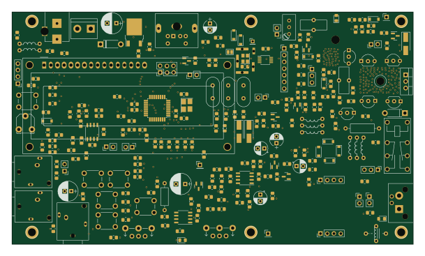 AVR/Arduino
RFBitBangSMT
profdc9
152 × 88 mm263 parts2LNo license221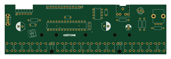 AVR/Arduino
Scout
oskitone
145.3 × 44.5 mm38 parts2LCustom license114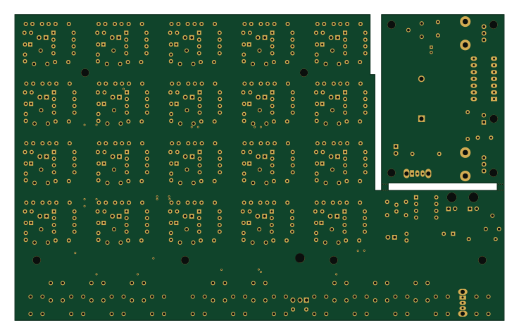
Poly555
184 × 114.8 mm248 parts2LCustom license91- schematic only · 48 partsNXP
Teensy 3 5 VGM Player YM2612 SN76489
AidanHockey5
48 partsAGPL-3.080 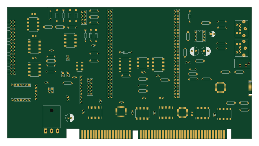
ISA FPGA v2
robfinch
223.3 × 120.1 mm104 parts4LNo license78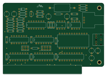
Isa opl2
skiselev
104.1 × 73.7 mm61 partsNo license36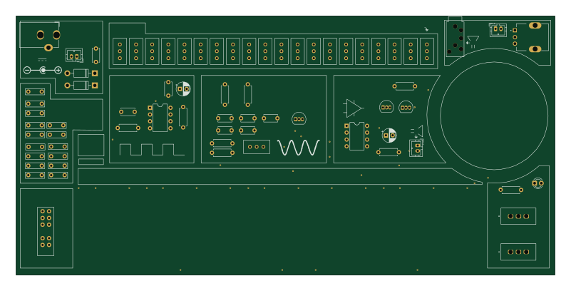
Touchtone555
DarcyJProjects
200 × 96 mm73 parts2LCERN-OHL-S-2.032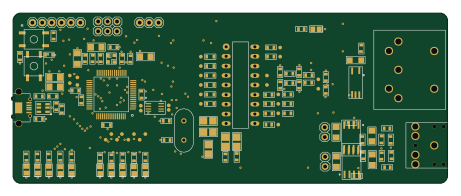 Silicon Labs
Ym2413 dev
andete
115 × 45 mm146 parts2LNo license25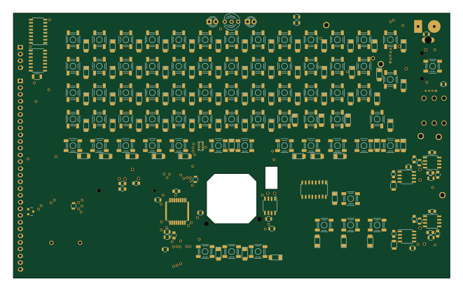 AVR/Arduino
Peripheral board
trollectronics
165 × 100 mm248 parts2LNo license22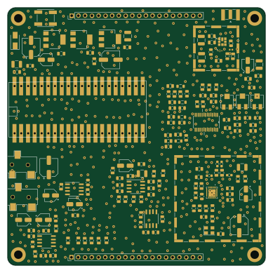 RP2040/RP2350
QO100 RX
barisdinc
97 × 97 mm162 parts2LGPL-3.020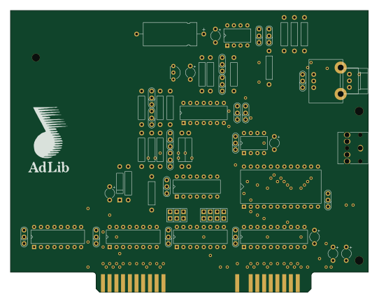
AdLib
monotech
135.3 × 106.7 mm61 parts2LNo license19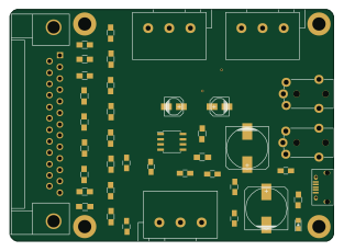
Pcb covox amp
yeokm1
78 × 56 mm39 parts2LMIT16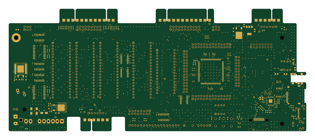 RP2040/RP2350
Commodore pet clone
DLehenbauer
262.5 × 108 mm258 parts2LCC0-1.013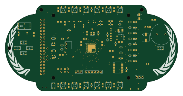
Dc25 spqr badge
netik
152.7 × 76.7 mm109 parts2LApache-2.011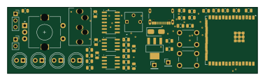 ESP32
Slider synth
udu3324
94.6 × 25 mm49 parts2LGPL-3.08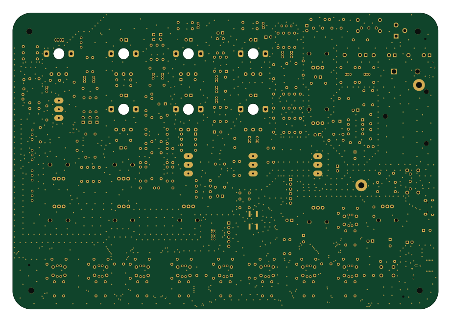 STM32
Liv Synth
SloBloLabs
230 × 159.9 mm273 parts2LMIT7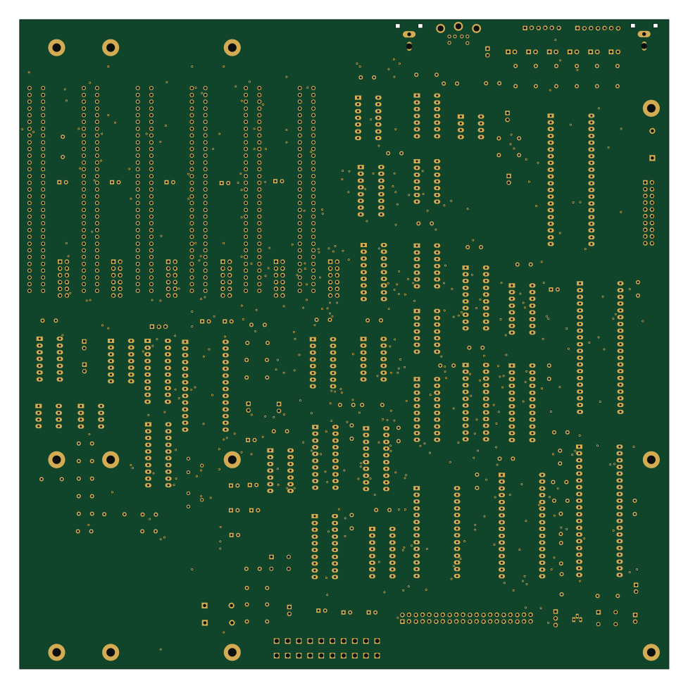 AVR/Arduino
CortexPC
danwerner21
244 × 244 mm155 parts2LNo license7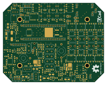
Ayn-4b
afiskon
114 × 89 mm272 parts2LMIT6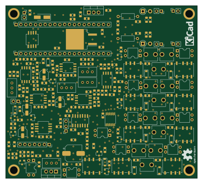
Ayn dc
100 × 90 mm220 parts2LMIT5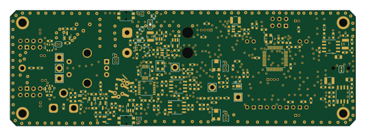
SignalSnagger
OpenARDF
133.4 × 44.4 mm200 parts4LMIT5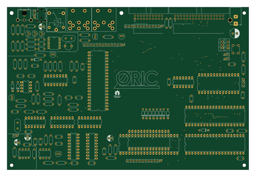
MetaphoricV2
OldWer
204.5 × 138 mm140 parts2LCC0-1.05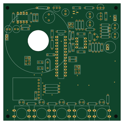 AVR/Arduino
Intercom
ukmaker
100 × 100 mm82 parts2LMIT5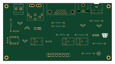
MZ80AV
Board-Folk
119 × 63.1 mm29 parts2LNo license5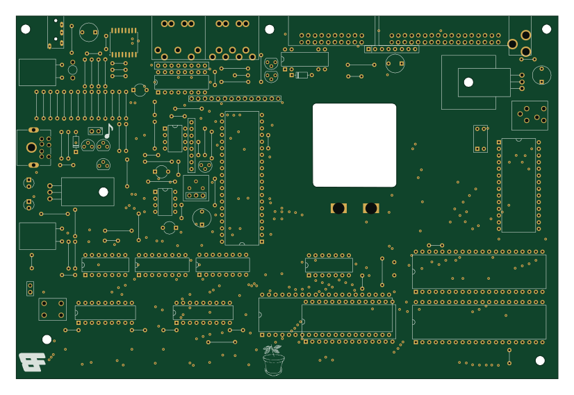
Oric
206.2 × 138.1 mm127 parts2LNo license4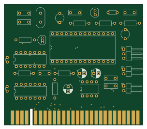
Zx talkman
zxinfo-diy-electronics
75.9 × 66 mm33 parts2LNo license4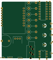 ESP8266
DraadloosDeurbel
pappavis
51.8 × 58.4 mm25 parts2LMIT4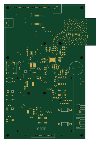 TI MSP430/CC
WALL-E
akrivka
102.6 × 150 mm92 parts2LNo license3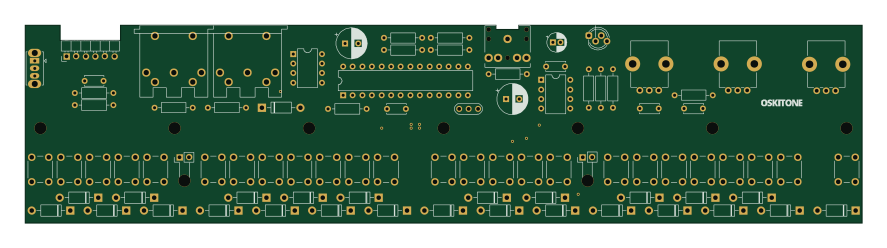 AVR/Arduino
SCOUT2
221.4 × 52.3 mm88 parts2LNo license3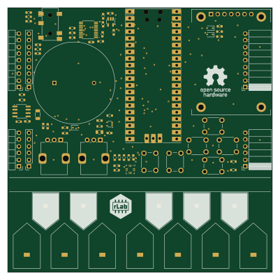 RP2040/RP2350
Project athena
reading-hackspace
100 × 100 mm77 parts2LNo license3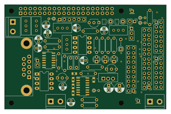 Raspberry Pi
Tetra Link boardIWQ
f1iwq2
85.2 × 55.4 mm70 parts2LNo license3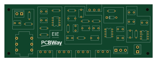
GuitarAmplifier-PCB-IE0308
RoMadrigal
158.5 × 57 mm33 parts4LMIT3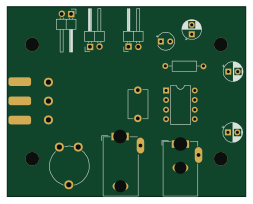
Zx spectrum amplifier
63.2 × 50.3 mm14 parts2LNo license3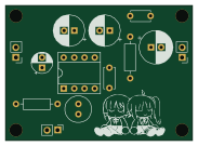
Lm386 amp
ctes091x
45.7 × 33 mm13 parts2LMIT3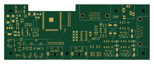 ESP32
NTerm2-S-FT231
RetepV
147.3 × 55.9 mm117 parts2LNo license2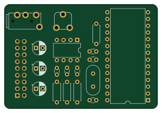
Speech
dimitrit
57 × 39 mm19 parts2LGPL-3.02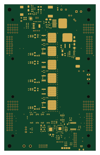 RP2040/RP2350
Solarpump
rivimey
100 × 160 mm424 parts4LNo license1
How designs wire the LM386
Read from the KiCad layouts of 115 open source designs, one per repository: what each pin of the LM386 connects to, and the resistors, capacitors and other passives placed on it.
- The P1 pin has a series capacitor on 107 of 115 designs, most often 220 µF (then 47 nF).
- The - pin is tied to GND on 89 of 115 designs (a signal on 26).
- The BYPASS pin has a capacitor to GND on 57 of 115 designs, most often 10 µF (then 100 nF).
- The V+ pin has a decoupling capacitor on 48 of 114 designs, most often 100 nF (then 100 µF).
| Pin | Connected to | Parts on the pin |
|---|---|---|
| GAINpin 1, 8 | Connected to: Not connected 54% · a signal 45% |
|
| -pin 2 | Connected to: GND 77% · a signal 23% | — |
| GNDpin 4 | Connected to: GND 90% | — |
| P1pin 5 | Connected to: Signal 99% |
|
| V+pin 6 | Connected to: 5V 74% · a signal 25% |
|
| BYPASSpin 7 | Connected to: Signal 63% · not connected 37% |
|
1 more pin varies from design to design. Connections count pins, parts count designs; values in brackets are how many parts had that value. Designs read include RFBitBanger by profdc9, RC6502 PSG by tebl, Scout by oskitone and Poly555 by oskitone.
The LM386 in open source designs
The gallery holds 156 open source boards using the LM386 from 126 GitHub repositories; a typical one measures about 100 × 72.4 mm and carries around 50 components.
88% are two-layer designs, the rest use four layers or more, and 31% carry an open source license.
The most starred is RFBitBangSMT by profdc9.
Parts used alongside the LM386
Microcontrollers on boards using the LM386
What boards using the LM386 are built for
LM386: common questions
Where can I find a LM386 reference design?
Each of the 156 boards on this page is a real design using the LM386. Open one to see how it is wired up, with the full BOM, a render of the layout and links to its KiCad files.
How is the LM386 P1 pin connected?
The P1 pin has a series capacitor on 107 of 115 designs, most often 220 µF (then 47 nF). Counted from the KiCad layouts of 115 open source designs using the LM386.
How is the LM386 - pin connected?
The - pin is tied to GND on 89 of 115 designs (a signal on 26). Counted from the KiCad layouts of 115 open source designs using the LM386.
How is the LM386 BYPASS pin connected?
The BYPASS pin has a capacitor to GND on 57 of 115 designs, most often 10 µF (then 100 nF). Counted from the KiCad layouts of 115 open source designs using the LM386.
What parts are used alongside the LM386?
The 74LS138, LM358, 74LS245, L7805 and SN76489 appear in the most repositories here.
Which microcontrollers do boards using the LM386 use?
Most are built on AVR/Arduino (21), ESP32 (9), RP2040/RP2350 (9) and STM32 (5).
How big is a typical board using the LM386?
The median is 100 × 72.4 mm, and 88% are two-layer designs.
What is the most popular open source board using the LM386?
By GitHub stars, RFBitBangSMT by profdc9, with 221 stars.
Can I simulate one of these boards using the LM386 before building it?
Yes. HardLabs turns a board's netlist and BOM into a working simulation, so you can boot and test firmware against it with no hardware on your desk.