
DP aux emulator

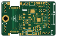
About the DP aux emulator PCB
DP aux emulator is an open source RP2040/RP2350 PCB design by JX5S, published on GitHub under the MIT license. It is a 6-layer board measuring 47 × 30 mm, with 82 components from 38 distinct parts.
Its main chip is the RP2040, from the RP2040/RP2350 family. Other key parts include the nW25Q64JVX, SN65MLVD200A and TPS54202DDC. By type, the board carries 28 resistors, 27 capacitors, 8 connectors, 6 diodes, 5 ICs and 3 jumpers.
From the project
Board for modifying traffic on DP-aux. Specifically, board is made for correcting false information provided by the PSVR2 making it not work on PC. Except for DP-aux, it is a passive extension of USB-C.
Hardware design files for a DP-aux emulation board, designed to allow connection of PSVR2 headsets to PC.
Prior to a March 2024 update of the PSVR2's firmware, the headset reported incorrect information via DP-aux, among others the EDID and DSC capability. A custom EDID can be set without additional hardware, however DSC options cannot be - so the emulator board was born.
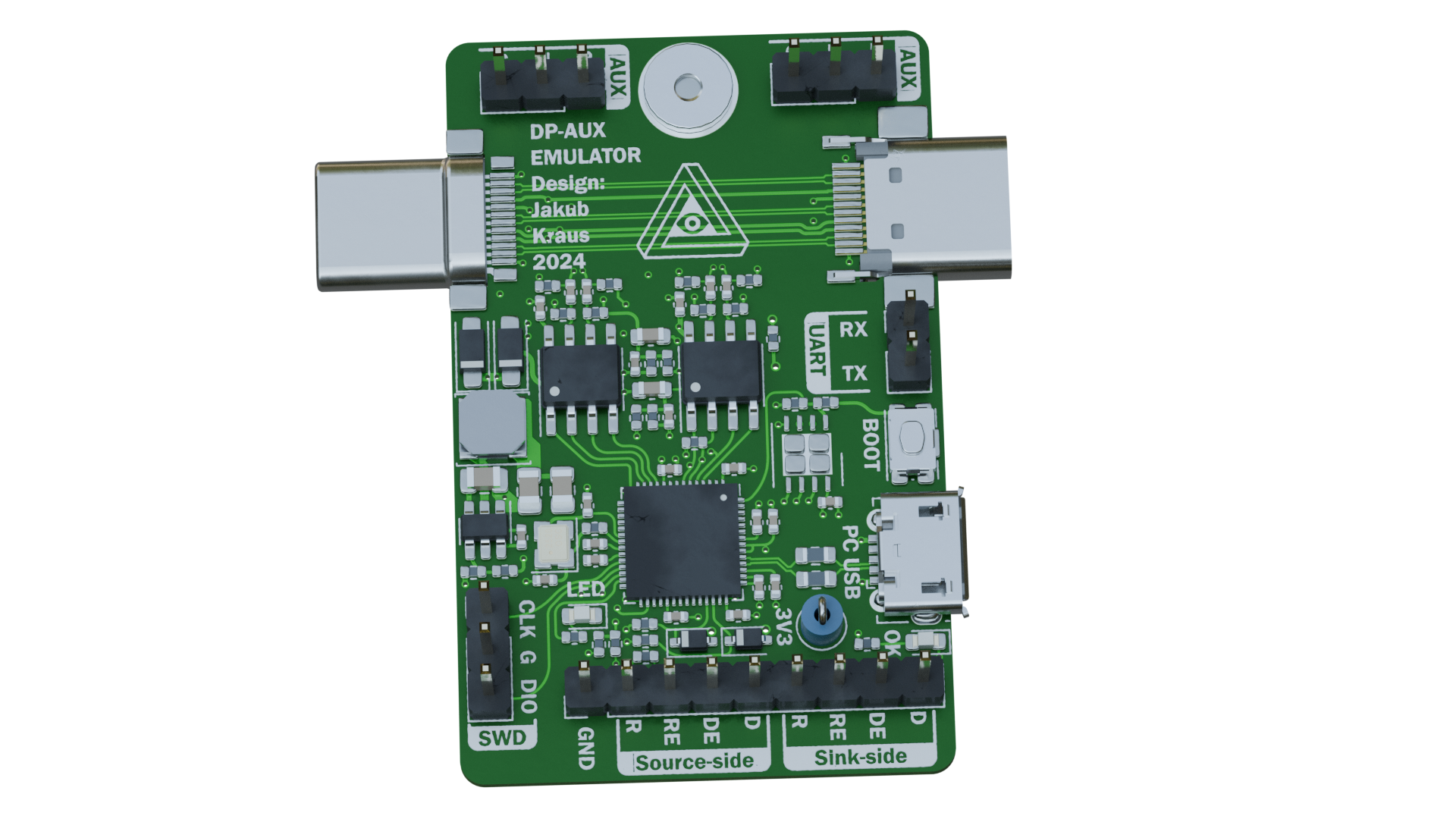
Main components on the DP aux emulator
DP aux emulator bill of materials (BOM)
82 components, 38 distinct parts — part numbers from the project's BOM.
| Qty | Part | Footprint | Refs |
|---|---|---|---|
| 1 | nW25Q64JVX | WSON-8-1EP_4x4mm_P0.8mm_EP2.6x3mm | U1 |
| 1 | RP2040 | QFN-56-1EP_7x7mm_P0.4mm_EP3.2x3.2mm | U2 |
| 2 | SN65MLVD200A | SOIC-8_3.9x4.9mm_P1.27mm | U3, U5 |
| 1 | TPS54202DDC | SOT-23-6 | U6 |
| 1 | 12MHz 12pF | Crystal_SMD_2520-4Pin_2.5x2.0mm | Y1 |
| 1 | USB_B_Micro | USB_Micro-B_Molex-105017-0001 | J1 |
| 1 | SWD | PinHeader_1x03_P2.54mm_Vertical | J2 |
| 1 | UART | PinHeader_1x02_P2.54mm_Vertical | J3 |
| 1 | USB_C_Plug | USB_C_VirtualLink_Plug | J4 |
| 2 | DP-AUX | PinHeader_1x03_P2.54mm_Vertical | J5, J7 |
| 1 | DEBUG HEADER | PinHeader_1x09_P2.54mm_Vertical | J6 |
| 1 | USB_C_Receptacle | USB_C_Straddle_Socket | J8 |
| 1 | M2_SMTSO2010CTJ | M2 solder nut | H1 |
| 1 | Disable | SolderJumper-2_P1.3mm_Open_RoundedPad1.0x1.5mm | JP1 |
| 1 | SolderJumper_3_Bridged12 | SolderJumper-3_P1.3mm_Bridged2Bar12_RoundedPad1.0x1.5mm | JP2 |
| 1 | SolderJumper_2_Closed | SolderJumper-2_P1.3mm_Bridged2Bar_RoundedPad1.0x1.5mm | JP3 |
| 1 | BOOT | C&K KMR223GLFG | SW1 |
| 1 | TestPoint | TestPoint_Loop_D1.80mm_Drill1.0mm_Beaded | TP3 |
| 2 | BZT52-C4V3S | D_SOD-323 Panjit | D1, D3 |
| 2 | Blue | LED_0603_1608Metric | D2, D7 |
Show 18 more
| Qty | Part | Footprint | Refs |
|---|---|---|---|
| 2 | SS14 | D_SOD-123FL | D4, D5 |
| 1 | 15u | L_Sunlord_SWPA4018S | L1 |
| 16 | 100n | C_0402_1005Metric | C1, C4, C5, C10, C11, C12, C13, C14 +8 |
| 2 | 15pF | C_0402_1005Metric | C2, C3 |
| 4 | 1uF | C_0402_1005Metric | C6, C7, C8, C9 |
| 2 | 10u | C_0603_1608Metric | C17, C25 |
| 1 | 10u | C_0805_2012Metric | C26 |
| 2 | 22u | C_0805_2012Metric | C27, C28 |
| 7 | 10K | R_0402_1005Metric | R1, R7, R8, R9, R17, R18, R28 |
| 3 | 1K | R_0402_1005Metric | R2, R5, R10 |
| 2 | 27R | R_0603_1608Metric | R3, R4 |
| 2 | 510R | R_0402_1005Metric | R6, R19 |
| 2 | 1M | R_0402_1005Metric | R11, R12 |
| 4 | 51R | R_0402_1005Metric | R13, R14, R20, R21 |
| 2 | 3K3 | R_0402_1005Metric | R15, R24 |
| 2 | 1K5 | R_0402_1005Metric | R16, R25 |
| 3 | 100K | R_0402_1005Metric | R22, R23, R26 |
| 1 | 22K | R_0402_1005Metric | R27 |
DP aux emulator design files
The KiCad project lives in the JX5S/DP_aux_emulator repository on GitHub; these links point at the commit this page was built from.
DP aux emulator: common questions
What microcontroller does the DP aux emulator use?
The DP aux emulator is built around the RP2040, from the RP2040/RP2350 family.
How big is the DP aux emulator PCB?
The DP aux emulator measures 47 × 30 mm, has 6 copper layers and is 0.8 mm thick.
How many components are on the DP aux emulator?
82 components, from 38 distinct parts, with part numbers taken from the project's own BOM. The full bill of materials is listed on this page.
Where can I download the DP aux emulator design files?
From the JX5S/DP_aux_emulator repository on GitHub, which has the KiCad layout, the schematic and the BOM; the links under Design files point to each one.
Can I use the DP aux emulator design in my own project?
Yes, under the terms of its MIT license, which JX5S chose for the repository.
Can I test firmware for the DP aux emulator without the hardware?
Yes. HardLabs builds a simulation of the board from its netlist and BOM, so you can run and debug RP2040/RP2350 firmware against it before you order a PCB.
Similar boards
 RP2040/RP2350
Open Book Abridged Edition
joeycastillo
85 × 115 mm29 parts2LCC-BY-SA-4.08.1k RP2040/RP2350
Corne
foostan
277.2 × 107.5 mm164 parts2LCC-BY-4.07.7k RP2040/RP2350
Corne
277.2 × 107.5 mm164 parts2LCC-BY-4.07.7k RP2040/RP2350
Msa
Mentra-Community
47.8 × 9.4 mm53 parts2LMIT1.2k RP2040/RP2350
Open Source Smart Glasses
93 × 10.5 mm80 parts4LMIT1.2k RP2040/RP2350
MSA
30.5 × 138 mm61 parts2LMIT1.2k