
KbxBinaryClock.v3.backup

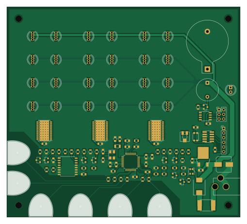
About the KbxBinaryClock.v3.backup PCB
KbxBinaryClock.v3.backup is an open source STM32 PCB design by kbx81, published on GitHub. It is a 2-layer board measuring 127 × 114.3 mm, with 123 components from 44 distinct parts.
Its main chip is the STM32F072CBTx, from the STM32 family. Other key parts include the TLC5947, LD1117S33TR, DS3231 and MAX485E. By type, the board carries 38 resistors, 25 capacitors, 24 LEDs, 10 transistors, 7 ICs and 6 test points.
It belongs with the sensors designs in this gallery.
From the project
RGB Binary Clock project files - PCB and source
RGB Binary Clock PCB project files for KiCad (v4/v5)
Detailing the process is a bit outside of what I plan to discuss here. There are plenty of resources out around the web already that will do a better job of explaining this process than I can. That said, there's not much to it -- the files you need are here and all you need to do (more or less) is upload them to your PCB fabricator of choice and, after a few days, they'll ship them to you. I've used OSHPark for the prototypes and I can assure you that they turn out fantastic (purple) boards.

Main components on the KbxBinaryClock.v3.backup
KbxBinaryClock.v3.backup bill of materials (BOM)
123 components, 44 distinct parts — part numbers from the project's BOM.
| Qty | Part | Footprint | Refs |
|---|---|---|---|
| 1 | STM32F072CBTx | LQFP-48_7x7mm_Pitch0.5mm | U1 |
| 3 | TLC5947 | HTSSOP-32_6.1x11mm_Pitch0.65mm_ThermalPad | U2, U3, U4 |
| 1 | LD1117S33TR | TO-252-2 | U5 |
| 1 | DS3231 | SOIC-16W_7.5x10.3mm_Pitch1.27mm | U6 |
| 1 | MAX485E | SOIC-8_3.9x4.9mm_Pitch1.27mm | U7 |
| 3 | 2N7002 | SOT-23 | Q1, Q2, Q3 |
| 1 | Q_Photo_NPN | LED_D5.0mm | Q4 |
| 6 | Q_NPN_BCE | SOT-23 | Q5, Q6, Q7, Q8, Q9, Q10 |
| 1 | 32.768 KHz | Crystal_SMD_3215-2pin_3.2x1.5mm | Y1 |
| 1 | 8 MHz | Crystal_SMD_5032-4pin_5.0x3.2mm | Y2 |
| 1 | Jack-DC | BARREL_JACK | J1 |
| 1 | Conn_01x06 | Pin_Header_Straight_1x06_Pitch2.54mm | J2 |
| 1 | Conn_02x03_Odd_Even | Pin_Header_Straight_2x03_Pitch2.54mm | J3 |
| 1 | STM32_SWD_USART | Pin_Header_Straight_2x05_Pitch1.27mm_SMD | P1 |
| 1 | CR2032 | Keystone_103_1x20mm-CoinCell | BT1 |
| 1 | Buzzer | Buzzer_12x9.5RM7.6 | BZ1 |
| 1 | ~2A | Fuse_SMD2920 | F1 |
| 1 | 100K | Potentiometer_Trimmer_Vishay_TS53YJ | RV1 |
| 1 | SW_Push | SW_SPST_KMR2 | SW1 |
| 1 | TouchPad1 | TouchPad1 | TP1 |
Show 24 more
| Qty | Part | Footprint | Refs |
|---|---|---|---|
| 1 | TouchPad2 | TouchPad1 | TP2 |
| 1 | TouchPad3 | TouchPad1 | TP3 |
| 1 | TouchPad4 | TouchPad1 | TP4 |
| 1 | TouchPad5 | TouchPad1 | TP5 |
| 1 | TouchPad6 | TouchPad1 | TP6 |
| 24 | LED_RGB_COMMON_ANODE | LED_D5.0mm-4 | LED1, LED2, LED3, LED4, LED5, LED6, LED7, LED8 +16 |
| 1 | LED_Dual_AACC | LED_Cree-PLCC4_3.2x2.8mm_CCW | D1 |
| 1 | S3A | D_SMC | D2 |
| 2 | 12.5 pF | C_0805 | C1, C2 |
| 2 | 10 pF | C_0805 | C3, C4 |
| 12 | 100 nF | C_0805 | C5, C6, C8, C9, C10, C17, C18, C19 +4 |
| 1 | 10 nF | C_0805 | C7 |
| 1 | 1 µF | C_0805 | C11 |
| 2 | 4.7 µF | C_0805 | C12, C13 |
| 3 | 47 nF | C_0805 | C14, C15, C16 |
| 1 | 100 µF | CP_Elec_8x10 | C20 |
| 1 | 10 µF | C_0805 | C22 |
| 3 | 1M | R_0805 | R1, R4, R5 |
| 14 | 1K | R_0805 | R2, R3, R8, R9, R10, R11, R12, R13 +6 |
| 12 | 10K | R_0805 | R6, R14, R15, R16, R17, R18, R19, R23 +4 |
| 1 | 100K | R_0805 | R7 |
| 3 | 4K7 | R_0805 | R21, R26, R31 |
| 3 | 24K6 | R_0805 | R22, R27, R32 |
| 2 | 3K3 | R_0805 | R36, R37 |
KbxBinaryClock.v3.backup design files
The KiCad project lives in the kbx81/RGBBinaryClock repository on GitHub; these links point at the commit this page was built from.
KbxBinaryClock.v3.backup: common questions
What microcontroller does the KbxBinaryClock.v3.backup use?
The KbxBinaryClock.v3.backup is built around the STM32F072CBTx, from the STM32 family.
How big is the KbxBinaryClock.v3.backup PCB?
The KbxBinaryClock.v3.backup measures 127 × 114.3 mm, has 2 copper layers and is 1.6 mm thick.
How many components are on the KbxBinaryClock.v3.backup?
123 components, from 44 distinct parts, with part numbers taken from the project's own BOM. The full bill of materials is listed on this page.
Where can I download the KbxBinaryClock.v3.backup design files?
From the kbx81/RGBBinaryClock repository on GitHub, which has the KiCad layout and the BOM; the links under Design files point to each one.
Can I use the KbxBinaryClock.v3.backup design in my own project?
The repository has no license, so all rights stay with kbx81. Use it as a reference, and ask the author before reusing the design.
Can I test firmware for the KbxBinaryClock.v3.backup without the hardware?
Yes. HardLabs builds a simulation of the board from its netlist and BOM, so you can run and debug STM32 firmware against it before you order a PCB.
More boards in RGBBinaryClock
Similar boards
 STM32
STM32LumenPnP Motherboard
opulo-inc
149 × 95 mm296 parts4LCC-BY-SA-4.03.7k STM32
STM32AxxSolder
AxxAxx
39 × 82.5 mm122 parts2LGPL-3.01.7k STM32
STM32AIOC
skuep
21 × 31.5 mm47 parts2LMIT1.4k STM32
STM32Ferris
pierrechevalier83
208.8 × 86.8 mm102 parts2LSHL-2.11.3k STM32
STM32176 pin board
rusefi
61.8 × 73.2 mm76 parts2LGPL-3.01.2k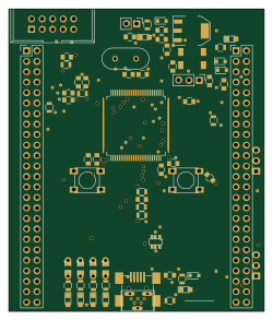 STM32
STM32Brain board STM32F407
61.8 × 73.2 mm69 parts2LGPL-3.01.2k