
Roomba esp wifi

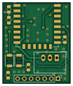
About the Roomba esp wifi PCB
Roomba esp wifi is an open source ESP8266 PCB design by kg333, published on GitHub under the CC-BY-SA-4.0 license. It is a 2-layer board measuring 25.4 × 30.5 mm, with 14 components from 7 distinct parts.
Its main chip is the ESP-12F, from the ESP8266 family. Other key parts include the TSR_1-2433. By type, the board carries 9 resistors, 2 ICs, 2 capacitors and 1 connector.
It belongs with the iot & wireless designs in this gallery.
From the project
Board for adding wifi using ESP-12 to Roomba 500/600 series
This project describes a board with an ESP-12 microcontroller and the following interfaces: UART - 3.3V, 5.0V tolerant Battery input - supports 4.75V - 36V GPIO - single pin at 3.3V 3.3V auxiliary output
It is intended for use with esp-roomba-mqtt by John Boiles, but may also be suitable for general use in battery-powered applications.
This board can be intially programmed in a similar fashion to a NodeMCU using your preferred Arduino programmer, but does require manual control using the PRGM and RST buttons. If using esp-roomba-mqtt, it may be programmed over Wifi after the initial flash.
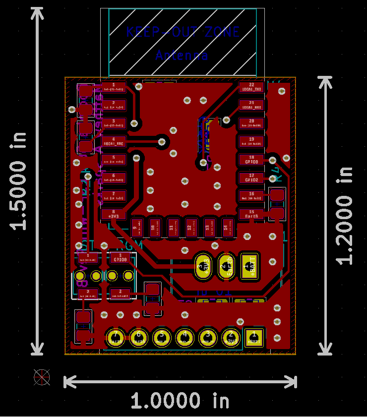
Main components on the Roomba esp wifi
Roomba esp wifi bill of materials (BOM)
14 components, 7 distinct parts.
| Qty | Part | Footprint | Refs |
|---|---|---|---|
| 1 | TSR_1-2433 | Converter_DCDC_TRACO_TSR-1_THT | U1 |
| 1 | ESP-12F | ESP-12E | U4 |
| 1 | Conn_01x07_Male | PinHeader_1x07_P2.54mm_Vertical | J1 |
| 2 | 10 uF | C_0805_2012Metric_Pad1.15x1.40mm_HandSolder | C1, C3 |
| 6 | 12K | R_0805_2012Metric_Pad1.15x1.40mm_HandSolder | R1, R2, R3, R4, R5, R7 |
| 1 | 6.04K | R_0805_2012Metric_Pad1.15x1.40mm_HandSolder | R6 |
| 2 | 470 | R_0805_2012Metric_Pad1.15x1.40mm_HandSolder | R8, R9 |
Roomba esp wifi design files
The KiCad project lives in the kg333/roomba_esp_wifi repository on GitHub; these links point at the commit this page was built from.
- Layoutroomba.kicad_pcb
Roomba esp wifi: common questions
What microcontroller does the Roomba esp wifi use?
The Roomba esp wifi is built around the ESP-12F, from the ESP8266 family.
How big is the Roomba esp wifi PCB?
The Roomba esp wifi measures 25.4 × 30.5 mm, has 2 copper layers and is 1.6 mm thick.
How many components are on the Roomba esp wifi?
14 components, from 7 distinct parts. The full bill of materials is listed on this page.
Where can I download the Roomba esp wifi design files?
From the kg333/roomba_esp_wifi repository on GitHub, which has the KiCad layout; the links under Design files point to each one.
Can I use the Roomba esp wifi design in my own project?
Yes, under the terms of its CC-BY-SA-4.0 license, which kg333 chose for the repository.
Can I test firmware for the Roomba esp wifi without the hardware?
Yes. HardLabs builds a simulation of the board from its netlist and BOM, so you can run and debug ESP8266 firmware against it before you order a PCB.
Similar boards
 ESP8266
ESP8266ControllerCircuit
stuartpittaway
75 × 30 mm20 parts2LCC-BY-NC-4.01.1k ESP8266
HASwitchPlate
aderusha
60 × 40 mm8 parts2LMIT738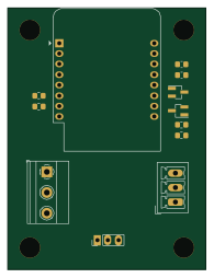 ESP8266
RatGDO-OpenSource-D1Mini-ESP8266
Kaldek
47.8 × 63.3 mm12 parts2LMIT506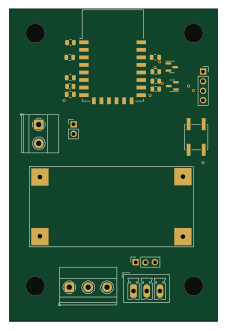 ESP8266
RatGDO-OpenSource-Bare-ESP8266
55 × 82.7 mm20 parts2LMIT506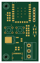 ESP8266
Goatgdo
32.9 × 53.3 mm23 parts2LMIT506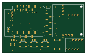 ESP8266
Iaq board
nkitanov
70.1 × 43.2 mm17 parts2LNo license398