
130 open source boards using the ESP-12F
Real designs built with the ESP-12F, from public GitHub projects: a quick way to see how others power, decouple and connect it. Each board comes with its KiCad files, full parts list and a render — and you can simulate its firmware on HardLabs.
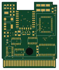 ESP8266
Wifi game boy cartridge
Staacks
51.4 × 61 mm28 parts2LNo license238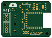 ESP8266
Pcb ws2812-wifi controller
klein0r
49.4 × 35.8 mm18 parts2LMIT80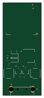 ESP8266
Mideahvac dongle
reneklootwijk
20 × 48.5 mm19 parts2LNo license75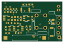 ESP8266
Window-Door sensor-Version-5
gadjet
31.5 × 20.6 mm30 parts2LGPL-2.070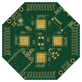 ESP8266
FreeEEG32
neuroidss
69.8 × 69.8 mm213 parts4LAGPL-3.039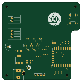 ESP8266
Velux controller
thorio
69.9 × 69.9 mm31 parts2LGPL-3.028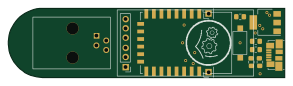 ESP8266
Pcb ttl ftdi esp adapter
73.1 × 18.3 mm11 parts2LMIT25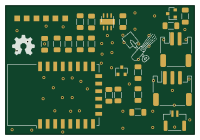 ESP8266
Esp8266-temperature humidity
amadeuspzs
49.9 × 34 mm23 parts2LNo license24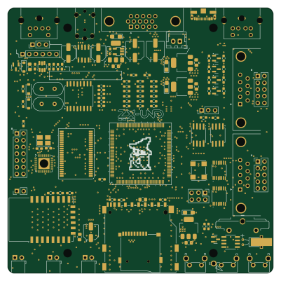 ESP8266
ZXUNO.1010
UzixLS
100 × 100 mm215 parts2LMIT23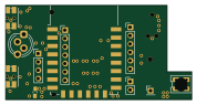 ESP8266
Ikea fyrtur
mjuhanne
44.5 × 22.5 mm42 parts4LMIT23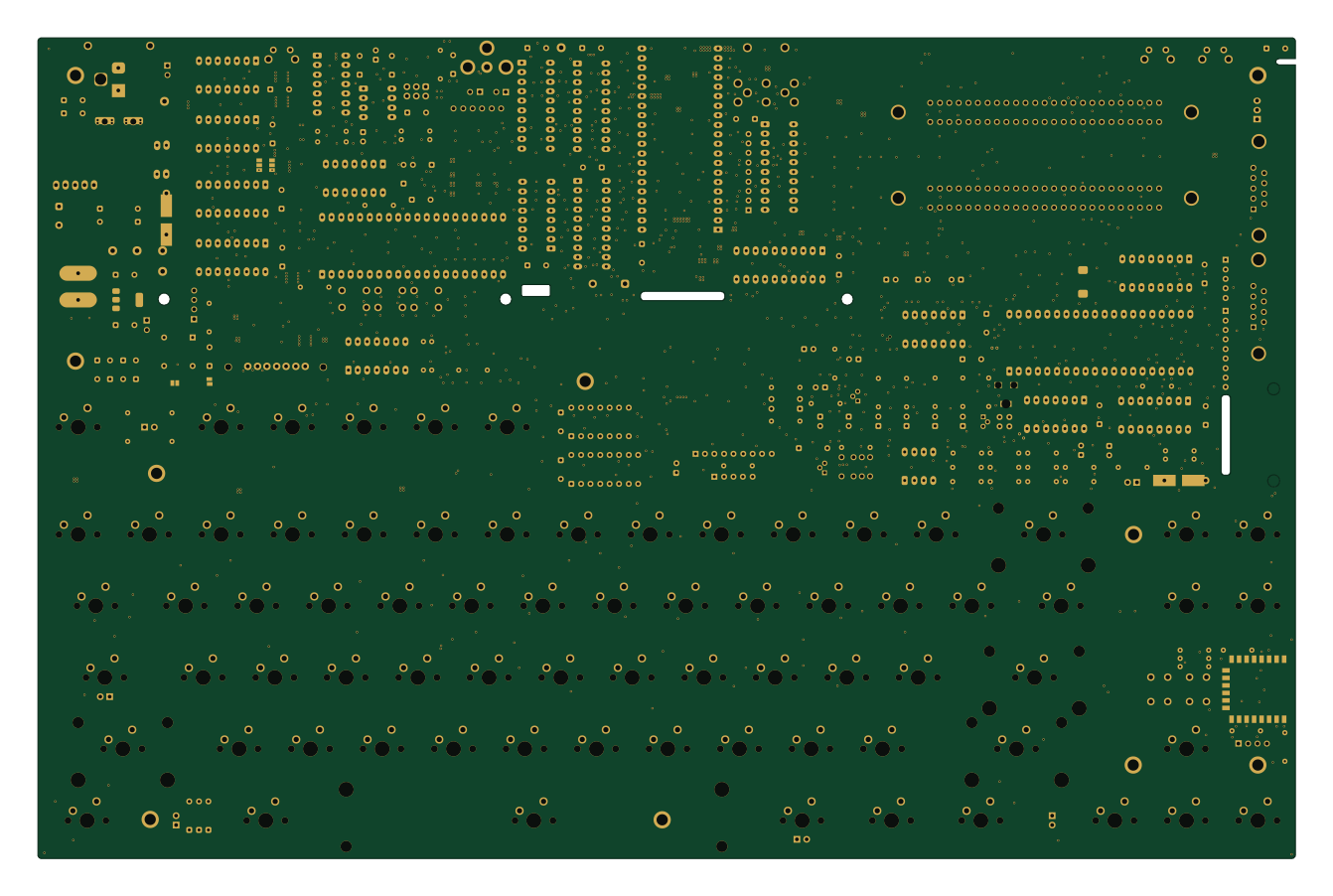 ESP8266
Stargate
leomanes
335 × 218.6 mm274 parts2LGPL-3.018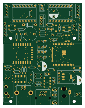 ESP32
OnStep-JUWEI-17
satakagi
67 × 87 mm72 parts2LGPL-3.017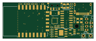 ESP8266
FineMotion-5
Kamilake
49.3 × 19.7 mm40 parts2LCERN-OHL-P-2.016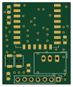 ESP8266
Roomba esp wifi
kg333
25.4 × 30.5 mm14 parts2LCC-BY-SA-4.016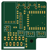 ESP8266
Blinder
nophead
42 × 45 mm24 parts4LGPL-3.09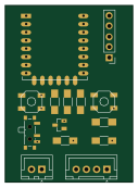 ESP8266
Environment monitor
theopensourcerer
31.1 × 43.2 mm14 parts2LNo license8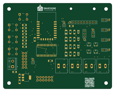 ESP8266
Bewaesserung
SmartHome-yourself
96.5 × 76.2 mm57 parts2LGPL-2.06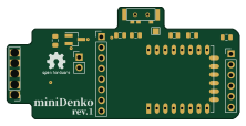 ESP8266
MiniDenko
likeablob
55.5 × 26.8 mm14 parts2LMIT6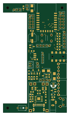 ESP8266
Another esp8266 sensor board
brev-dev
54.9 × 95 mm75 parts2LGPL-3.05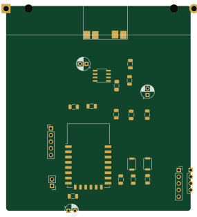 ESP8266
Kicad
josefadamcik
70.7 × 78.2 mm25 parts2LMIT5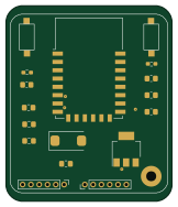 ESP8266
 Dev Board
ProZSolutions
40 × 47 mm17 parts2LNo license5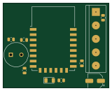 ESP8266
Smart fan
VGCH
40 × 32 mm41 parts2LNo license4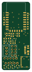 ESP8266
Weather station
mec-kon
24 × 57.8 mm73 parts2LGPL-3.03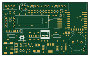 ESP8266
IoT Messenger
PR77
76.2 × 46.9 mm58 parts2LLGPL-3.03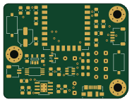 ESP8266
TWIN NODE2
MAATHES-THILAK-K
46.6 × 35.5 mm41 parts2LApache-2.03- schematic only · 30 partsRP2040/RP2350
PerryFi2
SanPollo
30 partsNo license3 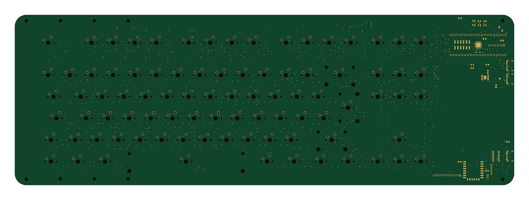 RP2040/RP2350
Kbn1
souptik-samanta
440 × 150 mm398 parts2LNo license2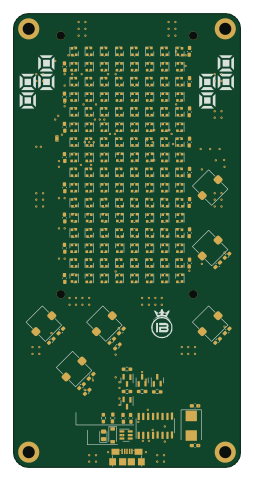 ESP8266
Tetris
arraym
60 × 120 mm224 parts2LNo license2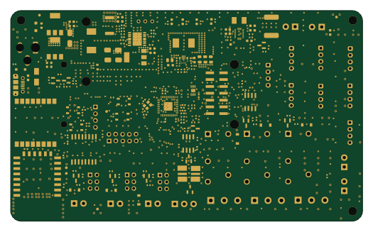 RP2040/RP2350
ANGAZA ELIMU
R-Mutura
131 × 78.5 mm207 parts4LNo license2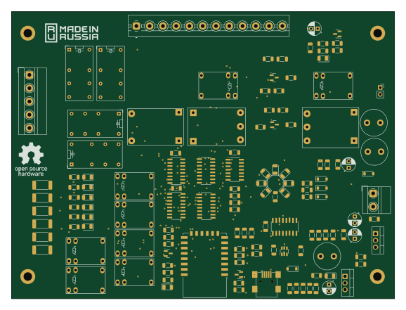 ESP8266
K9AY with wifi
ra0sms
144.2 × 108.1 mm137 parts2LMIT2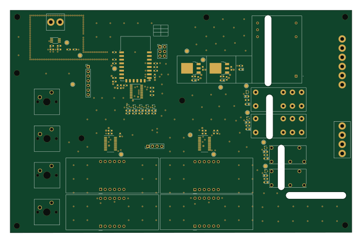 ESP8266
Reflowow oven controler
mickdassive
186 × 121.3 mm95 parts2LGPL-3.02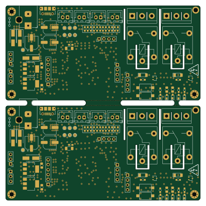 ESP8266
Electra-100x100mm-2x1-panel
Grehasopt
100 × 100 mm59 parts2LCERN-OHL-S-2.02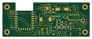 ESP8266
EVN Kaifa ESP MQTT
Tobias0110
79 × 31 mm59 parts2LGPL-2.02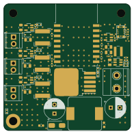 ESP8266
3ChannelCCdriver
wszeto9
49 × 49 mm58 parts2LNo license2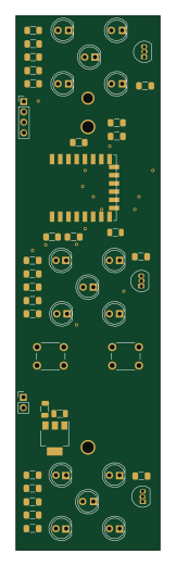 ESP8266
Traffic light
iley
35 × 130 mm50 parts2LNo license2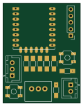 ESP8266
Esp8266-external temp sensor
29.5 × 38.1 mm14 parts2LNo license2
How designs wire the ESP-12F
Read from the KiCad layouts of 93 open source designs, one per repository: what each pin of the ESP-12F connects to, and the resistors, capacitors and other passives placed on it.
- The EN pin has a pull-up to 3.3V on 70 of 93 designs, most often 10 kΩ (then 12 kΩ).
- The GPIO15 pin has a resistor to GND on 69 of 93 designs, most often 10 kΩ (then 12 kΩ).
- The RST pin has a pull-up to 3.3V on 67 of 93 designs, most often 10 kΩ (then 12 kΩ).
- The SCLK pin is left unconnected on 78 of 89 designs (a signal on 11).
| Pin | Connected to | Parts on the pin |
|---|---|---|
| RSTpin 1 | Connected to: A connector 30% |
|
| ENpin 3 | Connected to: Signal 90% |
|
| VCCpin 8 | Connected to: 3.3V 88% |
|
| CS0pin 9 | Connected to: Not connected 84% | — |
| MISOpin 10 | Connected to: Not connected 85% | — |
| GPIO9pin 11 | Connected to: Not connected 83% · a signal 17% | — |
| GPIO10pin 12 | Connected to: Not connected 82% · a signal 18% | — |
| MOSIpin 13 | Connected to: Not connected 87% | — |
| SCLKpin 14 | Connected to: Not connected 88% | — |
| GNDpin 15 | Connected to: GND 86% | — |
| GPIO15pin 16 | Connected to: A connector 28% |
|
| GPIO2pin 17 | Connected to: A connector 25% · not connected 26% |
|
| GPIO0pin 18 | Connected to: A connector 36% |
|
9 more pins vary from design to design. Connections count pins, parts count designs; values in brackets are how many parts had that value. Designs read include RatGDO-OpenSource-Bare-ESP8266 by Kaldek, Wifi game boy cartridge by Staacks, Pcb ws2812-wifi controller by klein0r and Mideahvac dongle by reneklootwijk.
The ESP-12F in open source designs
The gallery holds 130 open source boards using the ESP-12F from 95 GitHub repositories; a typical one measures about 67 × 53 mm and carries around 40 components.
93% are two-layer designs, the rest use four layers or more, and 42% carry an open source license.
The most starred is RatGDO-OpenSource-Bare-ESP8266 by Kaldek.
Parts used alongside the ESP-12F
Microcontrollers on boards using the ESP-12F
What boards using the ESP-12F are built for
ESP-12F: common questions
Where can I find a ESP-12F reference design?
Each of the 130 boards on this page is a real design using the ESP-12F. Open one to see how it is wired up, with the full BOM, a render of the layout and links to its KiCad files.
What pull-up resistor is used on the ESP-12F EN pin?
The EN pin has a pull-up to 3.3V on 70 of 93 designs, most often 10 kΩ (then 12 kΩ). Counted from the KiCad layouts of 93 open source designs using the ESP-12F.
What resistor goes on the ESP-12F GPIO15 pin?
The GPIO15 pin has a resistor to GND on 69 of 93 designs, most often 10 kΩ (then 12 kΩ). Counted from the KiCad layouts of 93 open source designs using the ESP-12F.
What pull-up resistor is used on the ESP-12F RST pin?
The RST pin has a pull-up to 3.3V on 67 of 93 designs, most often 10 kΩ (then 12 kΩ). Counted from the KiCad layouts of 93 open source designs using the ESP-12F.
What parts are used alongside the ESP-12F?
The AMS1117-3.3, CH340C, AMS1117-5.0, AP2112K-3.3 and CH340G appear in the most repositories here.
Which microcontrollers do boards using the ESP-12F use?
Most are built on ESP8266 (122), RP2040/RP2350 (6) and ESP32 (2).
How big is a typical board using the ESP-12F?
The median is 67 × 53 mm, and 93% are two-layer designs.
What is the most popular open source board using the ESP-12F?
By GitHub stars, RatGDO-OpenSource-Bare-ESP8266 by Kaldek, with 506 stars.
Can I simulate one of these boards using the ESP-12F before building it?
Yes. HardLabs turns a board's netlist and BOM into a working simulation, so you can boot and test firmware against it with no hardware on your desk.