
PCB MotorECU

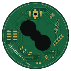
About the PCB MotorECU
PCB MotorECU is an open source PCB design by Knektium, published on GitHub under the CERN-OHL-1.2 license. It is a 2-layer board measuring 61 × 61 mm, with 27 components from 18 distinct parts.
Other key parts include the IFX9201SG, TLE4964, XMC1404_F064, TLE7251 and LM35-D. By type, the board carries 14 capacitors, 5 ICs, 4 connectors, 3 diodes and 1 resistor.
It belongs with the robotics & motion and sensors designs in this gallery.
From the project
The KiCad project for the PCB that is used as ECU for the Wolley Wheel and Fan modules.
This is the KiCad project for the PCB that is used as ECU for the Wolley Wheel and Fan modules.
It's a circular PCB that a brushed DC motor can be directly mounted on to be controlled by the driver and MCU onboard through CAN.
- Mabuchi RS-385PV-2465 - Mabuchi RS-365
Version 1.4: - Replaced the 4-pin connector with the new 5-pin connector. - Removed the battery power connector.
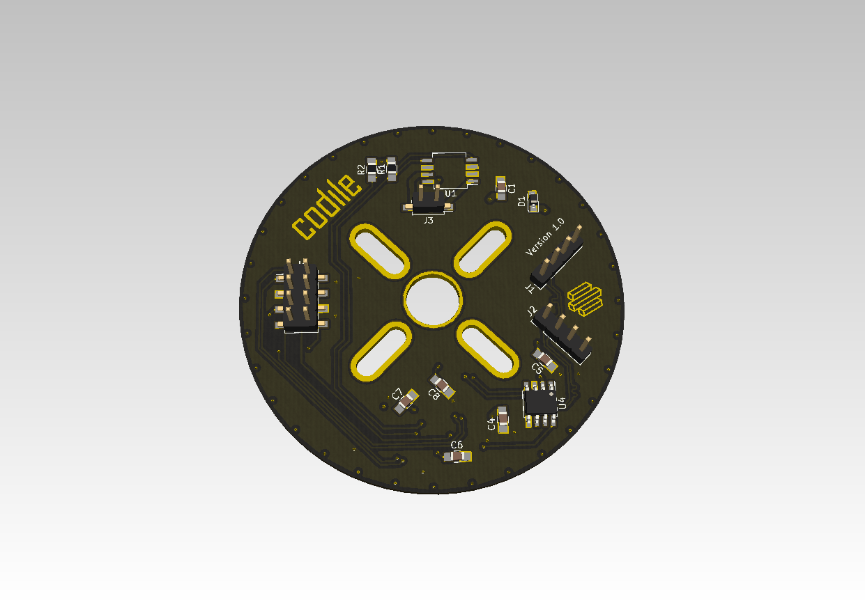
Main components on the PCB MotorECU
PCB MotorECU bill of materials (BOM)
27 components, 18 distinct parts.
| Qty | Part | Footprint | Refs |
|---|---|---|---|
| 1 | IFX9201SG | SOIC-12_HeatSlugs | U1 |
| 1 | TLE4964 | TSOT-23_HandSoldering | U2 |
| 1 | XMC1404_F064 | TQFP-64_10x10mm_Pitch0.5mm_Handsoldering | U3 |
| 1 | TLE7251 | SOIC-8_3.9x4.9mm_Pitch1.27mm | U4 |
| 1 | LM35-D | SOIC-8_3.9x4.9mm_P1.27mm | U5 |
| 2 | Conn_01x05 | PinHeader_1x05_P2.54mm_Vertical | J1, J2 |
| 1 | Conn_01x02 | PinHeader_1x02_P2.54mm_Vertical | J3 |
| 1 | Debug | Pin_Header_Straight_2x04_Pitch2.54mm_SMD | J4 |
| 1 | SMF5.0A | D_SOD-123F | D1 |
| 1 | SMF36A | D_SOD-123F | D2 |
| 1 | LED | C_0805_HandSoldering | D3 |
| 1 | 1uF | C_0805_HandSoldering | C1 |
| 1 | 47nF | C_0805_HandSoldering | C2 |
| 7 | 100nF | C_0805_HandSoldering | C3, C4, C5, C7, C8, C9, C14 |
| 1 | 220nF | C_0805_HandSoldering | C6 |
| 2 | 100uF | C_0805_HandSoldering | C10, C13 |
| 2 | 30nF | C_0805_HandSoldering | C11, C12 |
| 1 | 1K2 | C_0805_HandSoldering | R1 |
PCB MotorECU design files
The KiCad project lives in the Knektium/PCB_MotorECU repository on GitHub; these links point at the commit this page was built from.
- LayoutMotor_ECU.kicad_pcb
PCB MotorECU: common questions
How big is the PCB MotorECU?
The PCB MotorECU measures 61 × 61 mm, has 2 copper layers and is 1.6 mm thick.
How many components are on the PCB MotorECU?
27 components, from 18 distinct parts. The full bill of materials is listed on this page.
Where can I download the PCB MotorECU design files?
From the Knektium/PCB_MotorECU repository on GitHub, which has the KiCad layout; the links under Design files point to each one.
Can I use the PCB MotorECU design in my own project?
Yes, under the terms of its CERN-OHL-1.2 license, which Knektium chose for the repository.
Similar boards

Sensor smd
scottbez1
40 × 20 mm5 parts2LApache-2.04.2k
Sensors
StuckAtPrototype
15.2 × 9 mm14 parts4LApache-2.03.8k
Stack chan
stack-chan
50 × 50 mm33 parts2LApache-2.01.7k
Microphone
Mentra-Community
5.5 × 6.1 mm6 parts2LMIT1.2k
TemperaturePCB PANEL
stuartpittaway
116 × 75.5 mm178 parts2LCC-BY-NC-4.01.1k
Cube batteryboard
willem-pennings
95 × 95 mm4 parts2LGPL-3.01.1k