
Z2 io test01

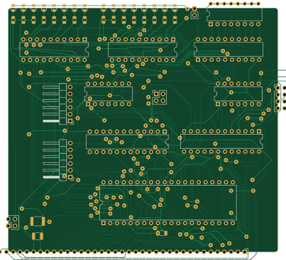
About the Z2 io test01 PCB
Z2 io test01 is an open source PCB design by krzys9876, published on GitHub under the MIT license. It is a 2-layer board measuring 100.5 × 91.1 mm, with 67 components from 19 distinct parts.
Other key parts include the 74LS154, 74HC245, 74LS32, Z8440 and 74HC374. By type, the board carries 24 resistors, 16 diodes, 9 ICs, 9 capacitors, 7 connectors and 1 fuse.
It belongs with the test & measurement designs in this gallery.
From the project
KiCad projects (schematics and boards) for a full-diy ZX Spectrum replica
All boards that I designed, etched and soldered to create a full-diy replica of ZX Spectrum. Kicad4 (just a keyboard) and Kicad5
This is NOT a cycle-perfect replica so do not expect to launch fancy demos on it. The project started as a breadboard simplest possible computer using Z80. Quite quickly I started thinking of making a replica of ZX Spectrum - the first computer I ever used as a kid. All I wanted was to:
Main components on the Z2 io test01
Z2 io test01 bill of materials (BOM)
67 components, 19 distinct parts.
| Qty | Part | Footprint | Refs |
|---|---|---|---|
| 2 | 74LS154 | DIP-24_W7.62mm | U1, U2 |
| 1 | 74HC245 | DIP-20_W7.62mm | U3 |
| 2 | 74LS32 | DIP-14_W7.62mm | U4, U9 |
| 1 | Z8440 | DIP-40_W15.24mm | U5 |
| 2 | 74HC374 | DIP-20_W7.62mm | U6, U8 |
| 1 | 74LVC1G14 | SOT-353_SC-70-5 | U7 |
| 1 | KB_SEL | PinHeader_2x02_P2.54mm_Vertical | J1 |
| 1 | CONN | PinHeader_1x37_P2.54mm_Horizontal | J2 |
| 1 | UART_A | PinHeader_1x06_P2.54mm_Horizontal | J3 |
| 1 | UART_B | PinHeader_1x06_P2.54mm_Horizontal | J4 |
| 1 | PW_SEL | PinHeader_2x02_P2.54mm_Vertical | J5 |
| 1 | CONN_OUT | PinHeader_2x04_P2.54mm_Vertical | J6 |
| 1 | LED_EN | PinHeader_1x02_P2.54mm_Vertical | J7 |
| 1 | Fuse | Fuse_1812_4532Metric | F1 |
| 1 | DIP_SW_C | DIP-16_W7.62mm | SW1 |
| 16 | LED | D_0805_2012Metric | D2, D3, D4, D5, D6, D7, D8, D9 +8 |
| 8 | 100n | C_1206_3216Metric | C1, C3, C4, C5, C6, C7, C8, C9 |
| 1 | 10u | C_1210_3225Metric | C2 |
| 24 | R | R_0805_2012Metric | R2, R3, R4, R5, R6, R7, R8, R9 +16 |
Z2 io test01 design files
The KiCad project lives in the krzys9876/ZX_Spectrum_diy repository on GitHub; these links point at the commit this page was built from.
Z2 io test01: common questions
How big is the Z2 io test01 PCB?
The Z2 io test01 measures 100.5 × 91.1 mm, has 2 copper layers and is 1.6 mm thick.
How many components are on the Z2 io test01?
67 components, from 19 distinct parts. The full bill of materials is listed on this page.
Where can I download the Z2 io test01 design files?
From the krzys9876/ZX_Spectrum_diy repository on GitHub, which has the KiCad layout; the links under Design files point to each one.
Can I use the Z2 io test01 design in my own project?
Yes, under the terms of its MIT license, which krzys9876 chose for the repository.
More boards in ZX_Spectrum_diy
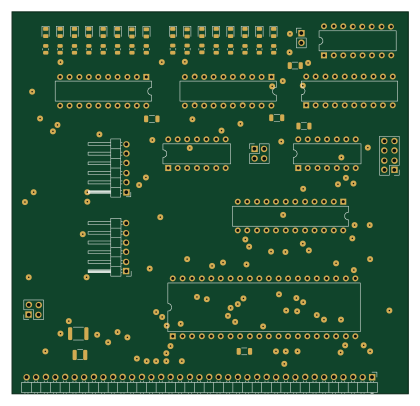
Z2 io
104.8 × 101 mm65 parts2LMIT2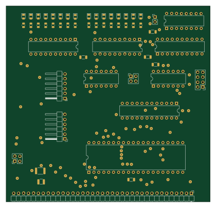
Z2 io test02
104.8 × 101 mm65 parts2LMIT2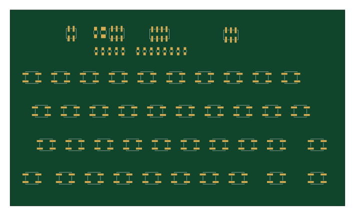
Keyb2 nofill
177.2 × 103.8 mm59 parts2LMIT2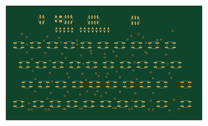
Keyb2
177.2 × 103.8 mm59 parts2LMIT2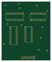
Zx2 clock
53.3 × 63.5 mm24 parts2LMIT2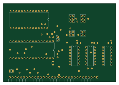
Zx2 mem
101 × 69.9 mm20 parts2LMIT2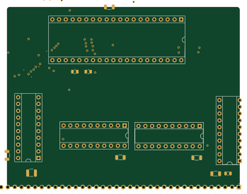
Zx2 cpu test01
87.1 × 67.5 mm18 parts2LMIT2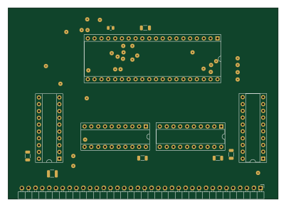
Zx2 cpu
100.3 × 71.1 mm18 parts2LMIT2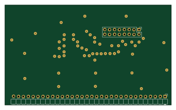
Zx2 fpga int
86.4 × 52.1 mm13 parts2LMIT2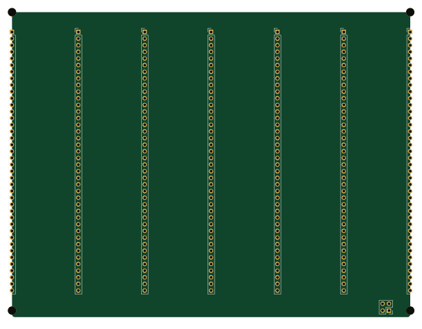
Zx2 backplane
152.4 × 116.8 mm12 parts2LMIT2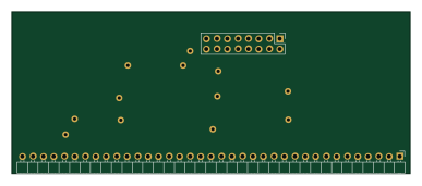
Zx2 keyb conn
96.5 × 39.4 mm10 parts2LMIT2
Similar boards
LevelShifter
gusmanb
28.3 × 39.8 mm21 parts2LGPL-3.05.0k
StackLink
52.3 × 10.5 mm5 parts2LGPL-3.05.0k
AnalyzerBoxPCB fork
52.7 × 47.9 mm54 parts4LGPL-3.05.0k
EleLab v2 Bus100
Chrismettal
100 × 100 mm37 parts2LGPL-3.0528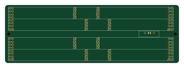
EleLab v2 Bus150
150 × 50 mm37 parts2LGPL-3.0528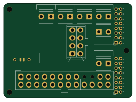
EleLab v2 PowerFeed
68 × 50 mm11 parts2LGPL-3.0528