
Pixfrog satellite

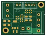
About the Pixfrog satellite PCB
Pixfrog satellite is an open source PCB design by Lefix2, published on GitHub under the MIT license. It is a 2-layer board measuring 39.9 × 31.5 mm, with 20 components from 14 distinct parts.
Other key parts include the 74LVC2G17 and LD1117S50TR_SOT223. By type, the board carries 6 resistors, 5 connectors, 4 diodes, 3 capacitors and 2 ICs.
It belongs with the rf & radio and displays & leds designs in this gallery.
From the project
Professional Art-Net pixel controller and dmx node — eight parallel channels, configured locally
The board half of pixfrogsatellite; its mechanical design (enclosure) is WIP** — the board mounts bare for now, H1/H2 tying its GND to the chassis or heatsink that carries it.
KiCad 10 project for the remote node that sits at the far end of a long LED cable run. The controller (or pixfrogshield) sends one channel's two signal lines down the cable; over distance the edges degrade and the strip voltage sags. The satellite re-squares the signal with a Schmitt-trigger buffer and injects local strip power**, so the LEDs see clean data and full voltage regardless of run length.
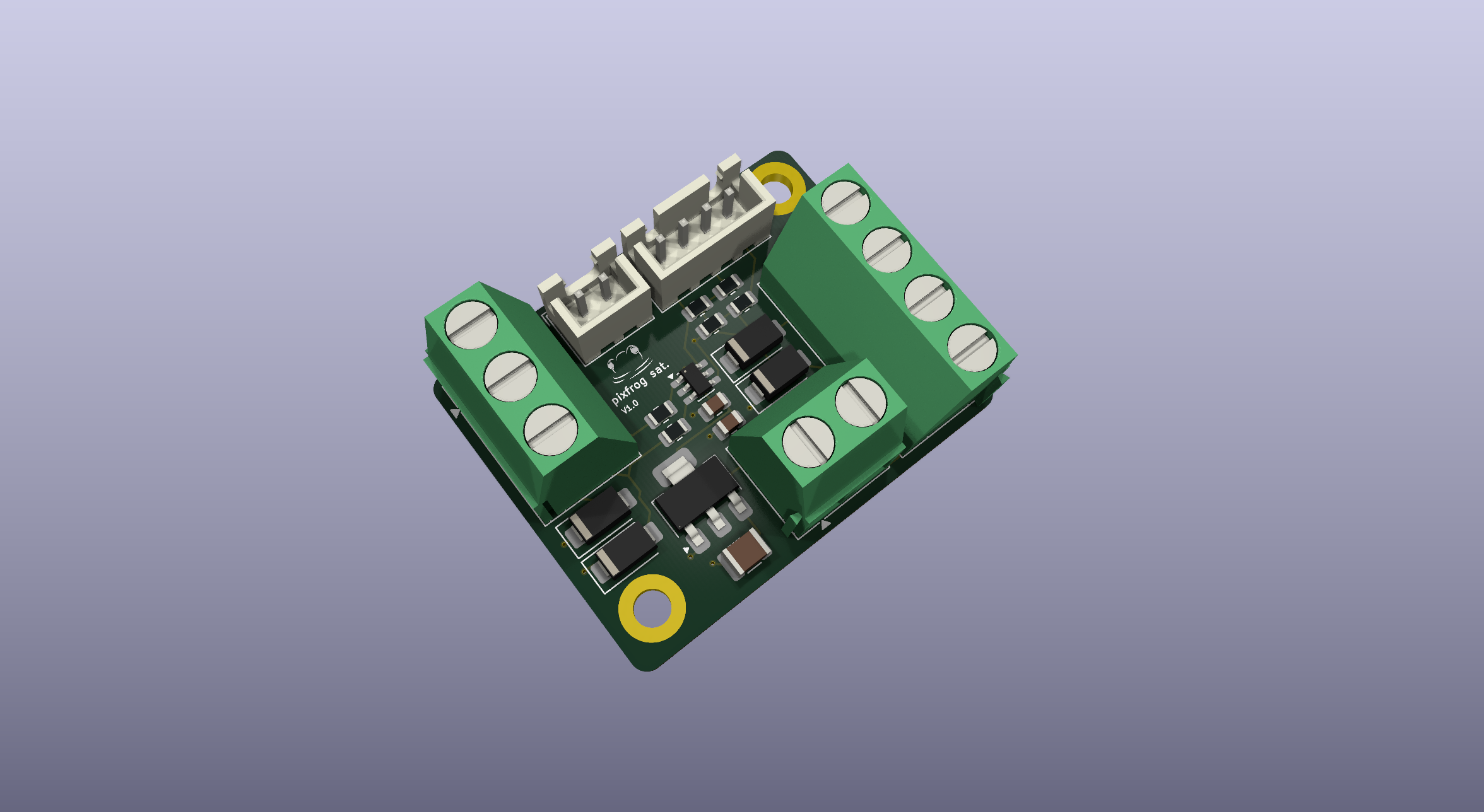
Main components on the Pixfrog satellite
Pixfrog satellite bill of materials (BOM)
20 components, 14 distinct parts — part numbers from the project's BOM.
| Qty | Part | Footprint | Refs |
|---|---|---|---|
| 1 | 74LVC2G17 | SC-74-6_1.55x2.9mm_P0.95mm | U1 |
| 1 | LD1117S50TR_SOT223 | SOT-223-3_TabPin2 | U2 |
| 1 | SCREW_TERMINAL_01X02 Screw_Terminal_01x02 | TerminalBlock_Phoenix_MKDS-1,5-2-5.08_1x02_P5.08mm_Horizontal | J1 |
| 1 | SCREW_TERMINAL_01X04 Screw_Terminal_01x04 | TerminalBlock_Phoenix_MKDS-1,5-4-5.08_1x04_P5.08mm_Horizontal | J2 |
| 1 | SCREW_TERMINAL_01X03 Screw_Terminal_01x03 | TerminalBlock_Phoenix_MKDS-1,5-3-5.08_1x03_P5.08mm_Horizontal | J3 |
| 1 | CONN_01X04 Conn_01x04 | JST_XH_B4B-XH-A_1x04_P2.50mm_Vertical | J4 |
| 1 | fan_out | JST_XH_B2B-XH-A_1x02_P2.50mm_Vertical | J5 |
| 4 | SMAJ5.0CA | D_SMA | D1, D2, D3, D4 |
| 1 | 100N 100n | C_0805_2012Metric | C1 |
| 1 | 10U 10u | C_0805_2012Metric | C2 |
| 1 | 10U 10u | C_1210_3225Metric | C3 |
| 2 | 33 | R_0805_2012Metric | R1, R2 |
| 2 | 39 | R_0805_2012Metric | R3, R4 |
| 2 | 249 | R_0805_2012Metric | R5, R6 |
Pixfrog satellite design files
The KiCad project lives in the Lefix2/pixfrog repository on GitHub; these links point at the commit this page was built from.
Pixfrog satellite: common questions
How big is the Pixfrog satellite PCB?
The Pixfrog satellite measures 39.9 × 31.5 mm, has 2 copper layers and is 1.6 mm thick.
How many components are on the Pixfrog satellite?
20 components, from 14 distinct parts, with part numbers taken from the project's own BOM. The full bill of materials is listed on this page.
Where can I download the Pixfrog satellite design files?
From the Lefix2/pixfrog repository on GitHub, which has the KiCad layout, the schematic and the BOM; the links under Design files point to each one.
Can I use the Pixfrog satellite design in my own project?
Yes, under the terms of its MIT license, which Lefix2 chose for the repository.
More boards in pixfrog
Similar boards

LevelShifterBreakout
scottbez1
15.2 × 20.3 mm5 parts2LApache-2.022.2k
View base
81.2 × 81.2 mm81 parts2LApache-2.022.2k
View screen
35 × 35 mm12 parts2LApache-2.022.2k
BM28B0.6-24DSBreakout
15.2 × 35.6 mm3 parts2LApache-2.022.2k
ChainlinkDriverTester
198.1 × 95.3 mm123 parts2LApache-2.04.2k
ChainlinkBase
98.4 × 190.5 mm119 parts2LApache-2.04.2k