
RIDE

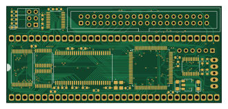
About the RIDE PCB
RIDE is an open source PCB design by LIV2, published on GitHub. It is a 4-layer board measuring 82.3 × 37.2 mm, with 62 components from 19 distinct parts.
Other key parts include the SST39SF010, 74LVC245, 74HCT245, W9812G6KH-6 and XC95144XL-TQ100. By type, the board carries 26 capacitors, 21 resistors, 9 ICs, 2 connectors, 1 crystal and 1 fuse.
From the project
IDE Off: Close to disable IDE RAM1/RAM2: Autoconfig RAM configuration |RAM1|RAM2|Size| |-|-|----| |Open|Open|8 MB| |Closed|Open|4 MB| |Open|Closed|2 MB| |Closed|Closed|Disable|
IDE Off: Close to disable IDE RAM1/RAM2: Autoconfig RAM configuration |RAM1|RAM2|Size| |-|-|----| |Open|Open|8 MB| |Closed|Open|4 MB| |Open|Closed|2 MB| |Closed|Closed|Disable|
To add the A0 Bonus RAM to the system you will need to use the addram command included in the RIDE-Software adf/lha found under Releases.
Alternatively you can add the bootrom module to a custom kickstart so that this is done automatically at every boot.
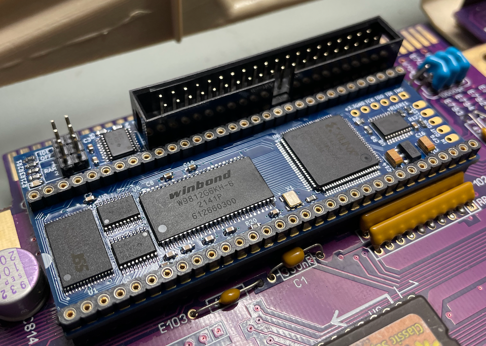
Main components on the RIDE
RIDE bill of materials (BOM)
62 components, 19 distinct parts — part numbers from the project's BOM.
| Qty | Part | Footprint | Refs |
|---|---|---|---|
| 1 | SST39SF010 | TSOP-I-32_11.8x8mm_P0.5mm | U1 |
| 2 | 74LVC245 | TSSOP-20_4.4x6.5mm_P0.65mm | U2, U3 |
| 3 | 74HCT245 | TSSOP-20_4.4x6.5mm_P0.65mm | U4, U8, U9 |
| 1 | W9812G6KH-6 | TSOP-II-54_22.2x10.16mm_P0.8mm | U5 |
| 1 | XC95144XL-TQ100 | TQFP-100_14x14mm_P0.5mm | U6 |
| 1 | AZ1117-3.3 | SOT-89-3 | U7 |
| 1 | 50MHZ 50MHz | Oscillator_SMD_Abracon_ASE-4Pin_3.2x2.5mm | X1 |
| 1 | C9138 IDE | IDC-Header_2x20_P2.54mm_Vertical | J1 |
| 1 | CONN_02X03_ODD_EVEN Conn_02x03_Odd_Even | PinHeader_2x03_P2.54mm_Vertical | J4 |
| 1 | AMIGA | DIP-64_W22.86mm | AMIGA1 |
| 1 | C21714343 Polyfuse 500mA Hold | Fuse_1206_3216Metric_Pad1.42x1.75mm_HandSolder | F1 |
| 1 | LED | LED_0603_1608Metric | D1 |
| 21 | 0.1U 0.1u | C_0603_1608Metric | C1, C2, C3, C4, C5, C6, C7, C8 +13 |
| 2 | 10U 10u | CP_EIA-3216-18_Kemet-A | C14, C15 |
| 2 | 10U 10u | C_0805_2012Metric_Pad1.18x1.45mm_HandSolder | C21, C25 |
| 1 | 47UF 47uF | CP_EIA-3216-18_Kemet-A_Pad1.58x1.35mm_HandSolder | C26 |
| 11 | 10K | R_0603_1608Metric | R1, R2, R3, R4, R5, R8, R10, R11 +3 |
| 7 | 33 | R_0603_1608Metric | R6, R7, R9, R13, R14, R18, R19 |
| 3 | 150 | R_0603_1608Metric | R12, R20, R21 |
RIDE design files
The KiCad project lives in the LIV2/RIDE repository on GitHub; these links point at the commit this page was built from.
- LayoutKicad/RIDE.kicad_pcb
- SchematicKicad/RIDE.kicad_sch
- BOMGerbers/RIDE_bom_jlc.csv
RIDE: common questions
How big is the RIDE PCB?
The RIDE measures 82.3 × 37.2 mm, has 4 copper layers and is 1.6 mm thick.
How many components are on the RIDE?
62 components, from 19 distinct parts, with part numbers taken from the project's own BOM. The full bill of materials is listed on this page.
Where can I download the RIDE design files?
From the LIV2/RIDE repository on GitHub, which has the KiCad layout, the schematic and the BOM; the links under Design files point to each one.
Can I use the RIDE design in my own project?
The repository has no license, so all rights stay with LIV2. Use it as a reference, and ask the author before reusing the design.