
Study

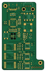
About the Study PCB
Study is an open source Microchip SAM PCB design by LukeAndreesen, published on GitHub. It is a 2-layer board measuring 46.3 × 75 mm, with 73 components from 28 distinct parts.
Its main chip is the ATSAMD21G18A-A, from the Microchip SAM family. Other key parts include the VCNL3040, 74HC595PW-Q100,118 and TLV73333PQDBVRQ1. By type, the board carries 36 resistors, 13 capacitors, 6 ICs, 4 diodes, 3 connectors and 3 switches.
From the project
A Study Timer PCB Project - hold yourself accountable by setting the timer, attaching your phone to the detector, and sitting in front of the module. If you get up or move your phone before the timer's done, you'll deal with alarms & other consequences ...
This project is a study timer that is meant to enforce productivity; an onboard IR sensor, as well as a daughter-board hall-effect sensor module detect a user's presence and ensure their phone is sitting on the desk and not in their hands. 3 daisy-chaineed shift registers control the 7-segment displays, and a magnetic buzzer and onboard LED's provide feedback and alerts. The devce connects to the user's computer via USB for power and serial connectivity with the UI which can be interacted with using the board's buttons and potentiometer dial. This was my first independent PCB board, and I…
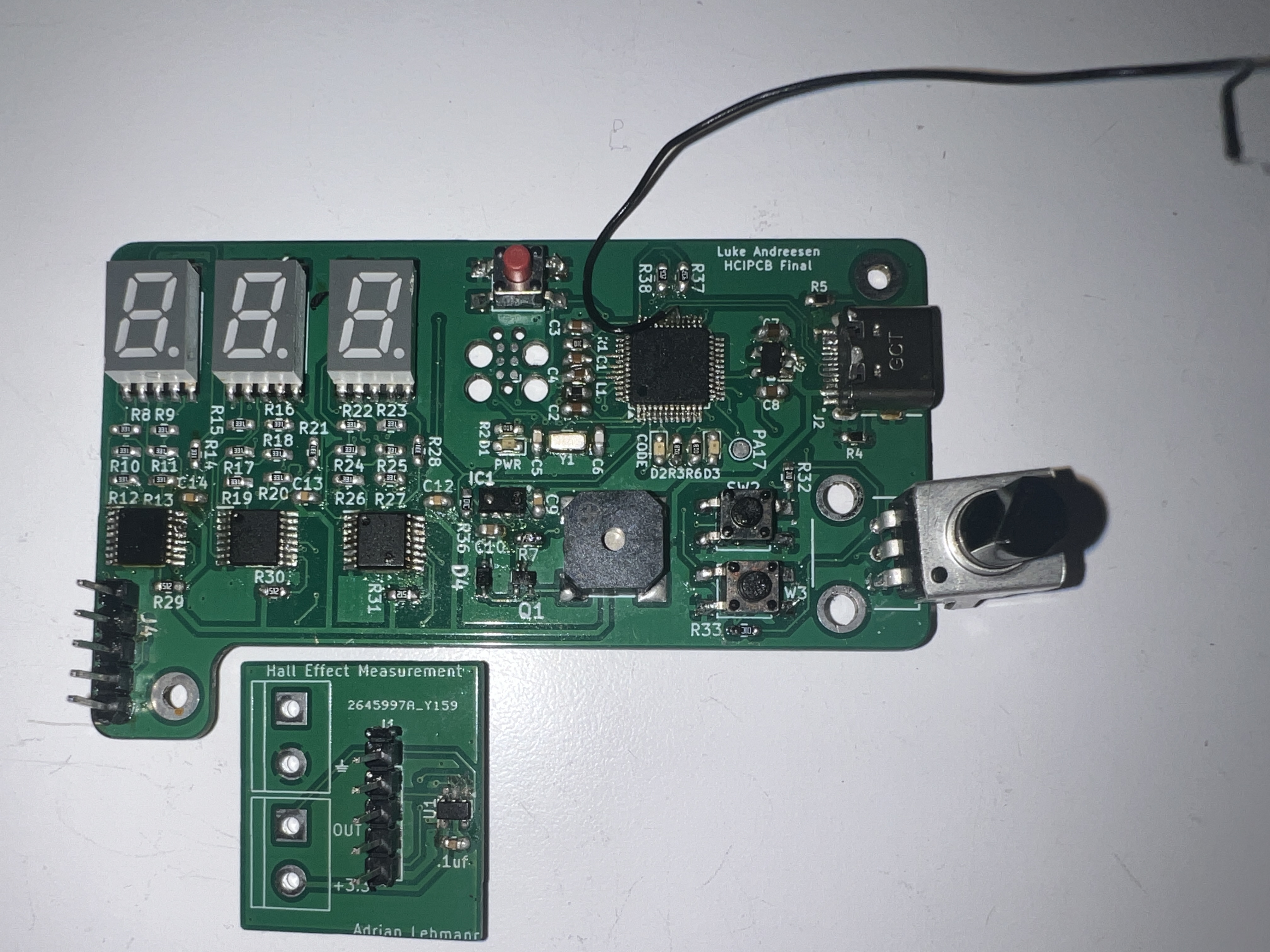
Main components on the Study
Study bill of materials (BOM)
73 components, 28 distinct parts — part numbers from the project's BOM.
| Qty | Part | Footprint | Refs |
|---|---|---|---|
| 1 | VCNL3040 | SON108P200X400X115-8N | IC1 |
| 3 | 74HC595PW-Q100,118 | SOP65P640X110-16N | IC2, IC3, IC4 |
| 1 | ATSAMD21G18A-A | TQFP-48_7x7mm_P0.5mm | U1 |
| 1 | TLV73333PQDBVRQ1 | SOT95P280X145-5N | U2 |
| 1 | Q_NPN_BCE | 2SA1588GRLF | Q1 |
| 1 | Crystal_Small | Crystal_SMD_3215-2Pin_3.2x1.5mm | Y1 |
| 1 | SWD_TAG-CONNECT | Tag-Connect_TC2030-IDC-FP_2x03_P1.27mm_Vertical | J1 |
| 1 | USB4105-GF-A | GCT_USB4105-GF-A | J2 |
| 1 | 10129379-905001BLF | HDRRA5W67P0X254_1X5_1270X254X241P | J4 |
| 3 | 157112V12700 | 157112V12700 | DS1, DS2, DS3 |
| 1 | CMT-8504-03-SMT-TR | CMT850403SMTTR | LS3 |
| 3 | SW_Push | SW_SPST_TL3305A | SW1, SW2, SW3 |
| 1 | PT01-B115D-B103 | PT01B115DB103 | VR1 |
| 1 | GREEN | LED_0603_1608Metric_Pad1.05x0.95mm_HandSolder | D1 |
| 2 | RED | LED_0603_1608Metric_Pad1.05x0.95mm_HandSolder | D2, D3 |
| 1 | D | SOD2713X115N | D4 |
| 1 | FB-30R | L_0603_1608Metric_Pad1.05x0.95mm_HandSolder | L1 |
| 4 | 0.1UF 0.1uF | C_0603_1608Metric_Pad1.08x0.95mm_HandSolder | C1, C2, C3, C4 |
| 2 | 22PF 22pF | C_0603_1608Metric_Pad1.08x0.95mm_HandSolder | C5, C6 |
| 2 | 1UF 1uF | C_0603_1608Metric_Pad1.08x0.95mm_HandSolder | C7, C8 |
Show 8 more
| Qty | Part | Footprint | Refs |
|---|---|---|---|
| 4 | 100NF 100nF | C_0603_1608Metric_Pad1.08x0.95mm_HandSolder | C9, C12, C13, C14 |
| 1 | 470NF 470nF | C_0603_1608Metric_Pad1.08x0.95mm_HandSolder | C10 |
| 4 | 10K 10k | R_0603_1608Metric_Pad0.98x0.95mm_HandSolder | R1, R32, R33, R36 |
| 3 | 1k | R_0603_1608Metric_Pad0.98x0.95mm_HandSolder | R2, R3, R6 |
| 5 | 5.1K 5.1k | R_0603_1608Metric_Pad0.98x0.95mm_HandSolder | R4, R5, R29, R30, R31 |
| 1 | 180 | R_0603_1608Metric_Pad0.98x0.95mm_HandSolder | R7 |
| 21 | 330 | R_0603_1608Metric_Pad0.98x0.95mm_HandSolder | R8, R9, R10, R11, R12, R13, R14, R15 +13 |
| 2 | 4.7K 4.7k | R_0603_1608Metric_Pad0.98x0.95mm_HandSolder | R37, R38 |
Study design files
The KiCad project lives in the LukeAndreesen/studyPCB repository on GitHub; these links point at the commit this page was built from.
Study: common questions
What microcontroller does the Study use?
The Study is built around the ATSAMD21G18A-A, from the Microchip SAM family.
How big is the Study PCB?
The Study measures 46.3 × 75 mm, has 2 copper layers and is 1.6 mm thick.
How many components are on the Study?
73 components, from 28 distinct parts, with part numbers taken from the project's own BOM. The full bill of materials is listed on this page.
Where can I download the Study design files?
From the LukeAndreesen/studyPCB repository on GitHub, which has the KiCad layout, the schematic and the BOM; the links under Design files point to each one.
Can I use the Study design in my own project?
The repository has no license, so all rights stay with LukeAndreesen. Use it as a reference, and ask the author before reusing the design.
Can I test firmware for the Study without the hardware?
Yes. HardLabs builds a simulation of the board from its netlist and BOM, so you can run and debug Microchip SAM firmware against it before you order a PCB.
Similar boards
 Microchip SAM
Fpgaboy
Wren6991
50 × 50 mm89 parts4LNo license508 Microchip SAM
Kira
kiibohd
366.9 × 114.3 mm400 partsCERN-OHL-1.2415 Microchip SAM
DSKY driver
benkrasnow
43 × 92.3 mm44 partsMIT258 Microchip SAM
Duet 2 Maestro
Duet3D
100 × 123 mm336 partsCERN-OHL-1.2257 Microchip SAM
Mainboard
pycubed
90.2 × 95.9 mm196 parts2LNo license96 Microchip SAM
Tiny4FSK
New-England-Weather-Balloon-Society
35.1 × 76.3 mm80 parts4LCERN-OHL-W-2.095