
PicUNO (Pico + UNO)

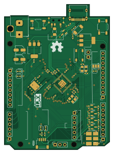
About the PicUNO (Pico + UNO) PCB
PicUNO (Pico + UNO) is an open source RP2040/RP2350 PCB design by MAATHES-THILAK-K, published on GitHub under the MIT license. It is a 2-layer board measuring 54.8 × 75.5 mm, with 72 components from 40 distinct parts.
Its main chip is the RP2040, from the RP2040/RP2350 family. Other key parts include the AMS1117-3.3, AMS1117-5.0 and W25Q32JVZP. By type, the board carries 20 resistors, 17 capacitors, 10 connectors, 6 jumpers, 5 diodes and 4 ICs.
It belongs with the iot & wireless and sensors designs in this gallery.
From the project
Arduino SMD version with In-Built Bluetooth and Gesture sensor
GrabCAD Link: https://grabcad.com/library/arduino-smd-1
This project is a compact, stylish, Arduino-compatible development board based on the ATmega328P-AU (TQFP). It includes several integrated peripherals making it ideal for wearable or IoT projects.
Gerber/ → Ready-to-export Gerber files for fabrication KiCad\Project/ → All source files for the schematic & layout images/ → (Optional) Screenshots, 3D renders of the board LICENSE → MIT License for reuse .gitignore → Standard for KiCad projects
Main components on the PicUNO (Pico + UNO)
PicUNO (Pico + UNO) bill of materials (BOM)
72 components, 40 distinct parts — part numbers from the project's BOM.
| Qty | Part | Footprint | Refs |
|---|---|---|---|
| 1 | RP2040 | QFN-56-1EP_7x7mm_P0.4mm_EP3.2x3.2mm | U1 |
| 1 | AMS1117-3.3 | SOT-223-3_TabPin2 | U3 |
| 1 | AMS1117-5.0 | SOT-223-3_TabPin2 | U4 |
| 1 | W25Q32JVZP | WSON-8-1EP_6x5mm_P1.27mm_EP3.4x4.3mm | U5 |
| 4 | BSS138 | SOT-23 | Q3, Q4, Q5, Q6 |
| 1 | \YSX321SL 12 Mhz | Crystal_SMD_3225-4Pin_3.2x2.5mm | Y1 |
| 1 | USB_C_RECEPTACLE_USB2.0 USB_C_Receptacle_USB2.0 | USB_C_Receptacle_G-Switch_GT-USB-7010ASV | J1 |
| 1 | SM04B-SRSS-TB_LF__SN_ | JST_SM04B-SRSS-TB_LF__SN_ | J2 |
| 1 | CONN_01X10_SOCKET Conn_01x10_Socket | PinSocket_1x10_P2.54mm_Vertical | J3 |
| 2 | CONN_01X08_SOCKET Conn_01x08_Socket | PinSocket_1x08_P2.54mm_Vertical | J4, J6 |
| 1 | CONN_01X06_PIN Conn_01x06_Pin | PinSocket_1x06_P2.54mm_Vertical | J5 |
| 1 | CONN_01X06_SOCKET Conn_01x06_Socket | PinSocket_1x06_P2.54mm_Vertical | J7 |
| 1 | CONN_01X03_PIN Conn_01x03_Pin | PinSocket_1x03_P2.54mm_Vertical | J8 |
| 1 | Barrel_Jack_Switch | BarrelJack_Horizontal | J9 |
| 1 | CONN_01X02_PIN Conn_01x02_Pin | PinHeader_1x02_P2.54mm_Vertical | J10 |
| 1 | Fuse | Fuse_1206_3216Metric_Pad1.42x1.75mm_HandSolder | F1 |
| 2 | JUMPER_2_BRIDGED Jumper_2_Bridged | SolderJumper-2_P1.3mm_Open_RoundedPad1.0x1.5mm | JP1, JP2 |
| 1 | JUMPER_3_OPEN Jumper_3_Open | SolderJumper-3_P1.3mm_Open_Pad1.0x1.5mm | JP3 |
| 1 | JUMPER_2_OPEN Jumper_2_Open | SolderJumper-2_P1.3mm_Open_RoundedPad1.0x1.5mm | JP4 |
| 2 | Jumper_2_Bridged | SolderJumper-2_P1.3mm_Open_RoundedPad1.0x1.5mm | JP5, JP6 |
Show 20 more
| Qty | Part | Footprint | Refs |
|---|---|---|---|
| 1 | SK-3296S-01-L3 | SK3296S01L3 | S1 |
| 1 | TACT SW | SW_SPST_TL3342 | SW1 |
| 1 | 4*4*1/5 SMD tact SW | SW_SPST_TL3342 | SW2 |
| 1 | SW_DPDT_X2 SW_DPDT_x2 | SW_CL-SB-22A-02T | SW3 |
| 1 | D_Schottky | D_SOD-128 | D1 |
| 1 | WS2812B | LED_WS2812B_PLCC4_5.0x5.0mm_P3.2mm | D2 |
| 1 | D_TVS_Dual_AAC | SOT-23 | D3 |
| 2 | LED | LED_0805_2012Metric_Pad1.15x1.40mm_HandSolder | D4, D5 |
| 2 | 27P 27p | C_0402_1005Metric_Pad0.74x0.62mm_HandSolder | C1, C2 |
| 9 | 100N 100n | C_0402_1005Metric_Pad0.74x0.62mm_HandSolder | C3, C4, C6, C7, C8, C9, C10, C11 +1 |
| 2 | 1u | C_0402_1005Metric_Pad0.74x0.62mm_HandSolder | C5, C12 |
| 1 | 10U 10u | C_0402_1005Metric_Pad0.74x0.62mm_HandSolder | C13 |
| 1 | 22PF 22pF | C_0402_1005Metric_Pad0.74x0.62mm_HandSolder | C14 |
| 2 | 10UF 10uF | CP_Elec_4x5.4 | C16, C17 |
| 2 | 220 | R_0402_1005Metric_Pad0.72x0.64mm_HandSolder | R1, R8 |
| 3 | 5.1K | R_0402_1005Metric_Pad0.72x0.64mm_HandSolder | R2, R3, R33 |
| 2 | 27R | R_0402_1005Metric_Pad0.72x0.64mm_HandSolder | R4, R5 |
| 2 | 1k | R_0402_1005Metric_Pad0.72x0.64mm_HandSolder | R6, R16 |
| 9 | 10K | R_0402_1005Metric_Pad0.72x0.64mm_HandSolder | R7, R11, R12, R13, R14, R20, R21, R22 +1 |
| 2 | 2.2K | R_0402_1005Metric_Pad0.72x0.64mm_HandSolder | R15, R17 |
PicUNO (Pico + UNO) design files
The KiCad project lives in the MAATHES-THILAK-K/Arduino-SMD repository on GitHub; these links point at the commit this page was built from.
PicUNO (Pico + UNO): common questions
What microcontroller does the PicUNO (Pico + UNO) use?
The PicUNO (Pico + UNO) is built around the RP2040, from the RP2040/RP2350 family.
How big is the PicUNO (Pico + UNO) PCB?
The PicUNO (Pico + UNO) measures 54.8 × 75.5 mm, has 2 copper layers and is 1.6 mm thick.
How many components are on the PicUNO (Pico + UNO)?
72 components, from 40 distinct parts, with part numbers taken from the project's own BOM. The full bill of materials is listed on this page.
Where can I download the PicUNO (Pico + UNO) design files?
From the MAATHES-THILAK-K/Arduino-SMD repository on GitHub, which has the KiCad layout, the schematic and the BOM; the links under Design files point to each one.
Can I use the PicUNO (Pico + UNO) design in my own project?
Yes, under the terms of its MIT license, which MAATHES-THILAK-K chose for the repository.
Can I test firmware for the PicUNO (Pico + UNO) without the hardware?
Yes. HardLabs builds a simulation of the board from its netlist and BOM, so you can run and debug RP2040/RP2350 firmware against it before you order a PCB.
More boards in Arduino-SMD
Similar boards
 RP2040/RP2350
Open Book Abridged Edition
joeycastillo
85 × 115 mm29 parts2LCC-BY-SA-4.08.1k RP2040/RP2350
Corne
foostan
277.2 × 107.5 mm164 parts2LCC-BY-4.07.7k RP2040/RP2350
Corne
277.2 × 107.5 mm164 parts2LCC-BY-4.07.7k RP2040/RP2350
LogicAnalyzer
gusmanb
57 × 55.2 mm6 parts2LGPL-3.05.0k RP2040/RP2350
Jitx design
55.5 × 65 mm26 parts4LGPL-3.05.0k RP2040/RP2350
Pro V2
kata0510
290.1 × 130 mm270 parts2LMIT2.3k