
MagicianCam4

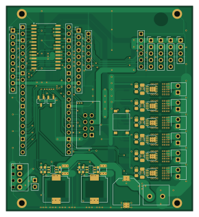
About the MagicianCam4 PCB
MagicianCam4 is an open source RP2040/RP2350 PCB design by magician-project, published on GitHub. It is a 2-layer board measuring 72 × 79 mm, with 110 components from 46 distinct parts.
Its main chip is the RaspberryPi_Pico_2, from the RP2040/RP2350 family. Other key parts include the TPS54302, MCP23018-E/SO and WIZ850io. By type, the board carries 50 resistors, 19 capacitors, 16 connectors, 15 transistors, 4 ICs and 2 diodes.
It belongs with the sensors and robotics & motion designs in this gallery.
From the project
Source code and documentation for the PCB and firmware of the main board of Magician sensor robot
Current revision of the Magician camera/sensing board, built around a Raspberry Pi Pico 2 (RP2350) instead of the Arduino Nano used in v1/. Firmware lives in src/pico2/.
- VL53L5CX multizone ToF sensor (8x8 = 64 distance zones) replacing the 3x VL53L0X single-zone sensors. - MCP23018 I²C I/O expander for buttons and light control, replacing the 74HC595 shift register chain. - Exposure-synced LED strobing with per-COB thermal budgeting, since the LED COBs are driven above their rated voltage and rely on strict pulse-width/duty-cycle limits to survive. - Ethernet connectivity kept compatible…
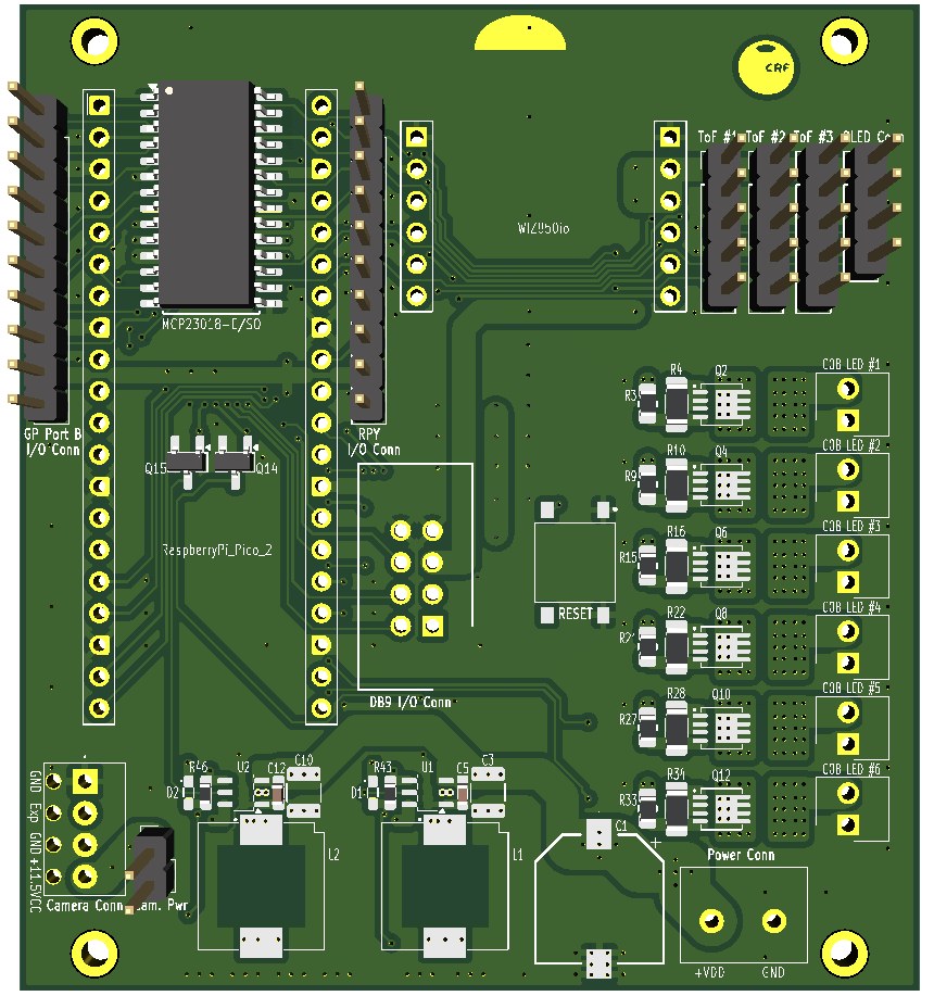
Main components on the MagicianCam4
MagicianCam4 bill of materials (BOM)
110 components, 46 distinct parts.
| Qty | Part | Footprint | Refs |
|---|---|---|---|
| 2 | TPS54302 | SOT-23-THIN-6_HANDSOLD | U1, U2 |
| 1 | MCP23018-E/SO | SOIC-28W_7.5x17.9mm_P1.27mm | U3 |
| 1 | WIZ850io | WIZ850IO | U4 |
| 1 | RaspberryPi_Pico_2 | RaspberryPi_Pico_THT | A1 |
| 8 | BSS138 | SOT-23_HANDSOLD2 | Q1, Q3, Q5, Q7, Q9, Q11, Q14, Q15 |
| 6 | PXN018-30QLJ BSZ180P03NS3GATMA1 | BSZ180P03NS3GATMA1 | Q2, Q4, Q6, Q8, Q10, Q12 |
| 1 | DMG2305UX | SOT-23_HANDSOLD2 | Q13 |
| 1 | 640456-2 COB LED #1 | 640456-2 | J1 |
| 1 | 640456-2 COB LED #2 | 640456-2 | J2 |
| 1 | 640456-2 COB LED #3 | 640456-2 | J3 |
| 1 | 640456-2 COB LED #4 | 640456-2 | J4 |
| 1 | 640456-2 COB LED #5 | 640456-2 | J5 |
| 1 | 640456-2 COB LED #6 | 640456-2 | J6 |
| 1 | Power Conn | TC0203620000G | J7 |
| 1 | Camera Conn | RS 790-1102 | J8 |
| 1 | ToF #1 | PinHeader_1x05_P2.54mm_Vertical | J9 |
| 1 | ToF #2 | PinHeader_1x05_P2.54mm_Vertical | J10 |
| 1 | ToF #3 | PinHeader_1x05_P2.54mm_Vertical | J11 |
| 1 | OLED Conn | PinHeader_1x04_P2.54mm_Vertical | J12 |
| 1 | DB9 I/O Conn | T821108A1S100CEU | J13 |
Show 26 more
| Qty | Part | Footprint | Refs |
|---|---|---|---|
| 2 | I/O Conn | PinHeader_1x10_P2.54mm_Vertical | J14, J15 |
| 1 | Cam. Pwr | PinHeader_1x02_P2.54mm_Vertical | J16 |
| 1 | PTS641 SM25 SMTR2 LFS RESET | PTS641SM25SMTR2LFS | S1 |
| 2 | LED | LSQ97601N1Q21 | D1, D2 |
| 2 | 10uH | SLF10165 | L1, L2 |
| 1 | 270u | EEHZS1H221P | C1 |
| 4 | 100n | C_0603_1608Metric_HANDSOLD | C2, C5, C12, C19 |
| 4 | 10u | GCM32EC71H106KA03K | C3, C4, C10, C11 |
| 2 | 100n | C_0805_2012Metric__HANDSOLD | C6, C13 |
| 1 | 100p | C_0603_1608Metric_HANDSOLD | C7 |
| 2 | 100u | CL32A107MQVNNNE | C8, C9 |
| 1 | 220p | C_0603_1608Metric_HANDSOLD | C14 |
| 4 | 22u | CL32A226KAJNNNE | C15, C16, C17, C18 |
| 6 | 100Ω | R_0603_1608Metric_HANDSOLD | R1, R7, R13, R19, R25, R31 |
| 7 | 15KΩ | R_0603_1608Metric_HANDSOLD | R2, R8, R14, R20, R26, R32, R42 |
| 6 | 475Ω | R_0805_2012Metric_Pad1.20x1.40mm_HandSolder | R3, R9, R15, R21, R27, R33 |
| 6 | 2.2KΩ | R_1206_3216Metric_Pad1.30x1.75mm_HandSolder | R4, R10, R16, R22, R28, R34 |
| 6 | 200KΩ | R_0603_1608Metric_HANDSOLD | R5, R11, R17, R23, R29, R35 |
| 6 | 200mΩ | R_2512_6332Metric_Pad1.40x3.35mm_HandSolder | R6, R12, R18, R24, R30, R36 |
| 3 | 4.7KΩ | R_0603_1608Metric_HANDSOLD | R37, R38, R48 |
| 3 | 4.7KΩ | R_0603_1608Metric | R39, R40, R41 |
| 2 | 100KΩ | R_0603_1608Metric_HANDSOLD | R43, R46 |
| 1 | 13.7KΩ | R_0603_1608Metric_HANDSOLD | R44 |
| 1 | 1.5KΩ | R_0603_1608Metric_HANDSOLD | R45 |
| 1 | 5.49KΩ | R_0603_1608Metric_HANDSOLD | R47 |
| 2 | 680KΩ | R_0603_1608Metric_HANDSOLD | R49, R50 |
MagicianCam4 design files
The KiCad project lives in the magician-project/magician_main_board repository on GitHub; these links point at the commit this page was built from.
MagicianCam4: common questions
What microcontroller does the MagicianCam4 use?
The MagicianCam4 is built around the RaspberryPi_Pico_2, from the RP2040/RP2350 family.
How big is the MagicianCam4 PCB?
The MagicianCam4 measures 72 × 79 mm, has 2 copper layers and is 1.6 mm thick.
How many components are on the MagicianCam4?
110 components, from 46 distinct parts. The full bill of materials is listed on this page.
Where can I download the MagicianCam4 design files?
From the magician-project/magician_main_board repository on GitHub, which has the KiCad layout and the schematic; the links under Design files point to each one.
Can I use the MagicianCam4 design in my own project?
The repository has no license, so all rights stay with magician-project. Use it as a reference, and ask the author before reusing the design.
Can I test firmware for the MagicianCam4 without the hardware?
Yes. HardLabs builds a simulation of the board from its netlist and BOM, so you can run and debug RP2040/RP2350 firmware against it before you order a PCB.
More boards in magician_main_board
Similar boards
 RP2040/RP2350
Open Book Abridged Edition
joeycastillo
85 × 115 mm29 parts2LCC-BY-SA-4.08.1k RP2040/RP2350
Corne
foostan
277.2 × 107.5 mm164 parts2LCC-BY-4.07.7k RP2040/RP2350
Corne
277.2 × 107.5 mm164 parts2LCC-BY-4.07.7k RP2040/RP2350
LogicAnalyzer
gusmanb
57 × 55.2 mm6 parts2LGPL-3.05.0k RP2040/RP2350
Jitx design
55.5 × 65 mm26 parts4LGPL-3.05.0k RP2040/RP2350
Pro V2
kata0510
290.1 × 130 mm270 parts2LMIT2.3k