
Wireless Slave

About the Wireless Slave PCB
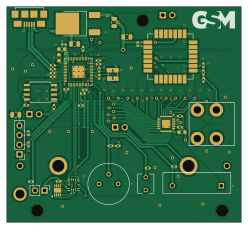
Wireless Slave is an open source RP2040/RP2350 PCB design by magnusbpt, published on GitHub. It is a 2-layer board measuring 62 × 57 mm, with 85 components from 52 distinct parts.
Its main chip is the SP485EN-L, from the RP2040/RP2350 family. Other key parts include the NCP1117IDT33T4G, ZMOD4410AI1R, SHT30-DIS-B10KS, ADP5587ACPZ-R7 and LoRa-E5. By type, the board carries 34 resistors, 26 capacitors, 8 ICs, 7 connectors, 3 switches and 1 transistor.
It belongs with the iot & wireless designs in this gallery.
Main components on the Wireless Slave
Wireless Slave bill of materials (BOM)
85 components, 52 distinct parts — part numbers from the project's BOM.
| Qty | Part | Footprint | Refs |
|---|---|---|---|
| 1 | NCP1117IDT33T4G | NCP1117IDT33T4G | IC1 |
| 1 | ZMOD4410AI1R | ZMOD4410AI1R | IC2 |
| 1 | SHT30-DIS-B10KS | SON50P250X250X100-9N-D | IC3 |
| 1 | ADP5587ACPZ-R7 | QFN50P400X400X80-25N-D | IC4 |
| 1 | LoRa-E5 | LoRaE5 | IC5 |
| 1 | EKMB1107111 | EKMB1107111 | U1 |
| 1 | SP485EN-L RP2040 | QFN-56-1EP_7x7mm_P0.4mm_EP3.2x3.2mm | U2 |
| 1 | L7805CV W25Q128JVS | SOIC-8_5.23x5.23mm_P1.27mm | U3 |
| 1 | BC847CW BCX56 | SOT-89-3 | Q1 |
| 1 | ABM3B-8.000MHZ-10-1-U-T 12MHz | X322512MSB4SI | Y1 |
| 1 | TB002-500-03BE ON/OFF | PinHeader_1x02_P2.54mm_Vertical | J1 |
| 1 | 10118192-0002LF | 101181920002LF | J2 |
| 1 | Conn_01x02 | PinHeader_1x02_P2.54mm_Vertical | J3 |
| 1 | TB002-500-04BE I2C | PinHeader_1x04_P2.54mm_Vertical | J4 |
| 1 | 54102-T06-00 Digital_in | PinHeader_1x02_P2.54mm_Vertical | J5 |
| 1 | 2337019-1 | 23370191 | J6 |
| 1 | FAN | PinHeader_1x02_P2.54mm_Vertical | J7 |
| 1 | Antenna | Event_alarm_antenna | AE1 |
| 1 | Battery_Cell | BHAA-3 | BT1 |
| 1 | 4081 | 4081 | S1 |
Show 32 more
| Qty | Part | Footprint | Refs |
|---|---|---|---|
| 1 | TL3305AF260QG SW_DIP_x06 | 2196LPST | SW1 |
| 1 | SW_DIP_x12 | 21912LPST | SW2 |
| 1 | Jumper_2_Open | SolderJumper-2_P1.3mm_Open_RoundedPad1.0x1.5mm | USB_Power1 |
| 1 | ESDA6V1-5W6 LED | LED_0805_2012Metric | D1 |
| 1 | 0Ω | R_0402_1005Metric | L1 |
| 3 | C0402C330J5GAC 100nf | C_0402_1005Metric | C1, C4, C5 |
| 2 | C0402C330J5GAC 10uf | C_0805_2012Metric | C2, C3 |
| 3 | 1uf | C_0603_1608Metric | C6, C7, C18 |
| 3 | 100nf | C_0402_1005Metric | C8, C9, C22 |
| 1 | CL21B334KBFNNNG 100nf | C_0402_1005Metric | C10 |
| 3 | C1005X7R1C104K050BC 100nf | C_0402_1005Metric | C11, C12, C14 |
| 1 | SCMQ14D474PRBB0 100nf | C_0402_1005Metric | C13 |
| 1 | GRM155R70J105KA12D 100nf | C_0402_1005Metric | C15 |
| 1 | CL31A107MQHNNWE 27pf | C_0402_1005Metric | C16 |
| 1 | 27pf | C_0402_1005Metric | C17 |
| 1 | 4,7uf | C_0402_1005Metric | C19 |
| 2 | NC | C_0402_1005Metric | C20, C21 |
| 4 | 10uf | C_0805_2012Metric | C23, C24, C25, C26 |
| 6 | RC0402FR-7W10KL 10KΩ | R_0402_1005Metric | R1, R9, R10, R13, R21, R22 |
| 2 | 0402WGF220JTCE 27Ω | R_0402_1005Metric | R2, R3 |
| 1 | 0402WGF220JTCE 10KΩ | R_0402_1005Metric | R4 |
| 9 | 10KΩ | R_0402_1005Metric | R5, R7, R26, R27, R28, R29, R30, R31 +1 |
| 1 | R_Photo | 02LDR1 | R6 |
| 1 | 0402WGF4702TCE 1KΩ | R_0402_1005Metric | R8 |
| 6 | 0402WGF1001TCE 10KΩ | R_0402_1005Metric | R11, R14, R18, R20, R23, R25 |
| 1 | 0402WGF2002TCE 10KΩ | R_0402_1005Metric | R12 |
| 1 | 0402WGF6800TCE 10KΩ | R_0402_1005Metric | R15 |
| 2 | CR0402-FX-9100GLF 10KΩ | R_0402_1005Metric | R16, R17 |
| 1 | ERJ-P06J620V 10KΩ | R_0402_1005Metric | R19 |
| 1 | 0402WGF2003TCE 10KΩ | R_0402_1005Metric | R24 |
| 1 | 70Ω | R_0402_1005Metric | R33 |
| 1 | 2.4KΩ | R_0603_1608Metric | R34 |
Wireless Slave design files
The KiCad project lives in the magnusbpt/Modbus-wireless repository on GitHub; these links point at the commit this page was built from.
Wireless Slave: common questions
What microcontroller does the Wireless Slave use?
The Wireless Slave is built around the SP485EN-L, from the RP2040/RP2350 family.
How big is the Wireless Slave PCB?
The Wireless Slave measures 62 × 57 mm, has 2 copper layers and is 1.6 mm thick.
How many components are on the Wireless Slave?
85 components, from 52 distinct parts, with part numbers taken from the project's own BOM. The full bill of materials is listed on this page.
Where can I download the Wireless Slave design files?
From the magnusbpt/Modbus-wireless repository on GitHub, which has the KiCad layout, the schematic and the BOM; the links under Design files point to each one.
Can I use the Wireless Slave design in my own project?
The repository has no license, so all rights stay with magnusbpt. Use it as a reference, and ask the author before reusing the design.
Can I test firmware for the Wireless Slave without the hardware?
Yes. HardLabs builds a simulation of the board from its netlist and BOM, so you can run and debug RP2040/RP2350 firmware against it before you order a PCB.
More boards in Modbus-wireless
Similar boards
 RP2040/RP2350
Open Book Abridged Edition
joeycastillo
85 × 115 mm29 parts2LCC-BY-SA-4.08.1k RP2040/RP2350
Corne
foostan
277.2 × 107.5 mm164 parts2LCC-BY-4.07.7k RP2040/RP2350
Corne
277.2 × 107.5 mm164 parts2LCC-BY-4.07.7k RP2040/RP2350
MSA
Mentra-Community
30.5 × 138 mm61 parts2LMIT1.2k RP2040/RP2350
Open Source Smart Glasses
93 × 10.5 mm80 parts4LMIT1.2k RP2040/RP2350
Msa
47.8 × 9.4 mm53 parts2LMIT1.2k