
Diy distortion pedal

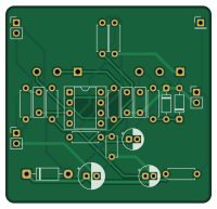
About the Diy distortion pedal PCB
Diy distortion pedal is an open source PCB design by maui-i, published on GitHub under the MIT license. It is a 2-layer board measuring 50 × 48 mm, with 25 components from 20 distinct parts.
Other key parts include the TL071. By type, the board carries 8 resistors, 7 capacitors, 4 connectors, 3 diodes and 1 IC.
It belongs with the audio and dev boards & breakouts designs in this gallery.
From the project
Beginner build guide for an MXR Distortion+ style guitar pedal: breadboard, perfboard and true-bypass footswitch
All of these pass with zero errors or warnings, and tools/export.sh re-runs them:
- ERC (electrical rules check) on the schematic. - DRC (design rules check) on the PCB: clearances, courtyards, silkscreen, unconnected pads. - Schematic parity: the PCB's footprints and nets match the schematic. - Connection list: tools/checknetlist.py compares the schematic's netlist with the connection list in docs/build-guide.md` (including footswitch, jacks and power), so the PCB and the guide describe the same circuit.
Main components on the Diy distortion pedal
Diy distortion pedal bill of materials (BOM)
25 components, 20 distinct parts — part numbers from the project's BOM.
| Qty | Part | Footprint | Refs |
|---|---|---|---|
| 1 | TL071 | DIP-8_W7.62mm_Socket | IC1 |
| 1 | IN | PinHeader_1x02_P2.54mm_Vertical | J1 |
| 1 | OUT | PinHeader_1x02_P2.54mm_Vertical | J2 |
| 1 | 9V IN | PinHeader_1x02_P2.54mm_Vertical | J3 |
| 1 | LED+ | PinHeader_1x01_P2.54mm_Vertical | J4 |
| 1 | C1M (GAIN) | Pot_16mm_PCB | RV1 |
| 1 | A10K (LEVEL) | Pot_16mm_PCB | RV2 |
| 2 | 1N34A | D_DO-35_SOD27_P7.62mm_Horizontal | D1, D2 |
| 1 | 1N5817 | D_DO-41_SOD81_P10.16mm_Horizontal | D3 |
| 1 | 10n | C_Rect_L7.2mm_W2.5mm_P5.00mm_FKS2_FKP2_MKS2_MKP2 | C1 |
| 1 | 47n | C_Rect_L7.2mm_W2.5mm_P5.00mm_FKS2_FKP2_MKS2_MKP2 | C2 |
| 1 | 1u | CP_Radial_D5.0mm_P2.00mm | C3 |
| 1 | 1n | C_Rect_L7.2mm_W2.5mm_P5.00mm_FKS2_FKP2_MKS2_MKP2 | C4 |
| 1 | 100u | CP_Radial_D6.3mm_P2.50mm | C5 |
| 1 | 100n | C_Disc_D5.0mm_W2.5mm_P5.00mm | C6 |
| 1 | 10u | CP_Radial_D5.0mm_P2.00mm | C7 |
| 3 | 1M | R_Axial_DIN0207_L6.3mm_D2.5mm_P7.62mm_Horizontal | R1, R2, R3 |
| 2 | 4.7k | R_Axial_DIN0207_L6.3mm_D2.5mm_P7.62mm_Horizontal | R4, R8 |
| 1 | 10k | R_Axial_DIN0207_L6.3mm_D2.5mm_P7.62mm_Horizontal | R5 |
| 2 | 100k | R_Axial_DIN0207_L6.3mm_D2.5mm_P7.62mm_Horizontal | R6, R7 |
Diy distortion pedal design files
The KiCad project lives in the maui-i/diy-distortion-pedal repository on GitHub; these links point at the commit this page was built from.
Diy distortion pedal: common questions
How big is the Diy distortion pedal PCB?
The Diy distortion pedal measures 50 × 48 mm, has 2 copper layers and is 1.6 mm thick.
How many components are on the Diy distortion pedal?
25 components, from 20 distinct parts, with part numbers taken from the project's own BOM. The full bill of materials is listed on this page.
Where can I download the Diy distortion pedal design files?
From the maui-i/diy-distortion-pedal repository on GitHub, which has the KiCad layout, the schematic and the BOM; the links under Design files point to each one.
Can I use the Diy distortion pedal design in my own project?
Yes, under the terms of its MIT license, which maui-i chose for the repository.
Similar boards
KLOR
GEIGEIGEIST
160.2 × 118.3 mm79 parts2LGPL-3.01.2k
134pin 7-967288-1
rusefi
139.7 × 73.7 mm38 parts2LGPL-3.01.2k
Breakout 60pin EEC-IV
139.7 × 62.2 mm15 parts2LGPL-3.01.2k
88 Pin Vag Breakout
142 × 58 mm91 parts2LGPL-3.01.2k
Eecv breakout
140.8 × 53.7 mm9 parts4LGPL-3.01.2k
Breakout 112pin Connector
174 × 58 mm39 parts2LGPL-3.01.2k