
Wro-2025-galaxy raiders

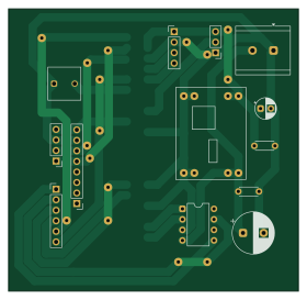
About the Wro-2025-galaxy raiders PCB
Wro-2025-galaxy raiders is an open source PCB design by mbit237, published on GitHub under the MIT license. It is a 2-layer board measuring 70 × 68 mm, with 14 components from 14 distinct parts.
By type, the board carries 7 connectors, 4 capacitors, 2 ICs and 1 switch.
It belongs with the robotics & motion and sensors designs in this gallery.
From the project
This repository contains the full stack for the robot: electronics (PCB design and fabrication artifacts), sensors (2D LiDAR, gyro, wheel encoders, compass), decision logic (landmark-based localisation and odometry that are fused using a complementary filter), navigation (path pl
This repository contains the full stack for the robot: electronics (PCB design and fabrication artifacts), sensors (2D LiDAR, gyro, wheel encoders, compass), decision logic (landmark-based localisation and odometry that are fused using a complementary filter), navigation (path planning, proportional steering), colour detection for the Obstacle Challenge (Raspberry Pi Camera–based colour blob detection for green and red), and a set of utilities for calibration, plotting, as well as testing.
Wro-2025-galaxy raiders bill of materials (BOM)
14 components, 14 distinct parts.
| Qty | Part | Footprint | Refs |
|---|---|---|---|
| 1 | ~ | DIP-8_W7.62mm | U1 |
| 1 | ~ | Voltage_Regulator_MP1584 | U3 |
| 1 | Screw_Terminal_01x02 | TerminalBlock_TE_282834-2_1x02_P5.08mm_Horizontal | J1 |
| 1 | Motor_Encoder_Conn_01x06_Pin | PinHeader_1x06_P2.54mm_Vertical | J2 |
| 1 | Raspi_Conn_02x20 | PinHeader_2x20_P2.54mm_Vertical_SMD | J3 |
| 1 | ComPass_Conn_01x04_Pin | PinHeader_1x04_P2.54mm_Vertical | J4 |
| 1 | Lidar_Conn_01x04_Pin | PinHeader_1x04_P2.54mm_Vertical | J5 |
| 1 | Servo_Conn_01x03_Pin | PinHeader_1x03_P2.54mm_Vertical | J6 |
| 1 | Gyro_Conn_01x08_Pin | PinHeader_1x08_P2.54mm_Vertical | J7 |
| 1 | SW_Push | Tact_Switch_TL59AF160Q_E-Switch | SW1 |
| 1 | 470uF | CP_Radial_D10.0mm_P5.00mm | C1 |
| 1 | 22uF | CP_Radial_D5.0mm_P2.50mm | C2 |
| 1 | 0.1uF | C_Disc_D4.3mm_W1.9mm_P5.00mm | C3 |
| 1 | 1uF | C_Disc_D4.3mm_W1.9mm_P5.00mm | C4 |
Wro-2025-galaxy raiders design files
The KiCad project lives in the mbit237/wro-2025-galaxy-raiders repository on GitHub; these links point at the commit this page was built from.
Wro-2025-galaxy raiders: common questions
How big is the Wro-2025-galaxy raiders PCB?
The Wro-2025-galaxy raiders measures 70 × 68 mm, has 2 copper layers and is 1.6 mm thick.
How many components are on the Wro-2025-galaxy raiders?
14 components, from 14 distinct parts. The full bill of materials is listed on this page.
Where can I download the Wro-2025-galaxy raiders design files?
From the mbit237/wro-2025-galaxy-raiders repository on GitHub, which has the KiCad layout and the schematic; the links under Design files point to each one.
Can I use the Wro-2025-galaxy raiders design in my own project?
Yes, under the terms of its MIT license, which mbit237 chose for the repository.
Similar boards
Sensor smd
scottbez1
40 × 20 mm5 parts2LApache-2.04.2k
Sensors
StuckAtPrototype
15.2 × 9 mm14 parts4LApache-2.03.8k
Stack chan
stack-chan
50 × 50 mm33 parts2LApache-2.01.7k
Microphone
Mentra-Community
5.5 × 6.1 mm6 parts2LMIT1.2k
TemperaturePCB PANEL
stuartpittaway
116 × 75.5 mm178 parts2LCC-BY-NC-4.01.1k
Cube batteryboard
willem-pennings
95 × 95 mm4 parts2LGPL-3.01.1k