
Battery can monitor

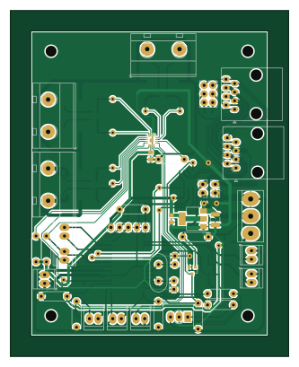
About the Battery can monitor PCB
Battery can monitor is an open source PIC PCB design by mbouyer, published on GitHub under the BSD-2-Clause license. It is a 2-layer board measuring 82 × 102 mm, with 67 components from 35 distinct parts.
Its main chip is the PIC18F27Q84, from the PIC family. Other key parts include the PAC1953-1, TLE9250VSJXUMA1 and LDL1117S50R. By type, the board carries 20 resistors, 15 connectors, 8 diodes, 8 capacitors, 6 fuses and 4 ICs.
It belongs with the power & battery designs in this gallery.
From the project
12V battery monitoring
This project includes 2 boards for a service 12V Pb battery monitoring.
The main board monitors the battery voltage and current, using a microchip PAC1953 chip and a precision shunt resistor. It uses a pic18f with integrated CAN controller, and connects to a CAN bus network. Along with instant voltage and current values, the pic18f will be able to compute and report the battery SoC. As the PAC1953 has 3 channels, it will also be able to monitor other sources, like solar panel or the engine battery. The main battery will be monitored with an external, high current shunt resistor (100A/50mV)…
Main components on the Battery can monitor
Battery can monitor bill of materials (BOM)
67 components, 35 distinct parts.
| Qty | Part | Footprint | Refs |
|---|---|---|---|
| 1 | PIC18F27Q84 | SOIC-28W_7.5x17.9mm_P1.27mm | U1 |
| 1 | PAC1953-1 | VQFN-16-1EP_3x3mm_P0.5mm_EP1.1x1.1mm | U2 |
| 1 | TLE9250VSJXUMA1 | SOIC-8_3.9x4.9mm_P1.27mm | U4 |
| 1 | LDL1117S50R | SOT-223-3_TabPin2 | U6 |
| 1 | BSS123 | SOT-23 | Q1 |
| 1 | ZXMN3A01FTA | SOT-23 | Q2 |
| 1 | 10Mhz | Crystal_HC18-U_Vertical | Y1 |
| 1 | sense3 | TerminalBlock_MetzConnect_Type703_RT10N02HGLU_1x02_P9.52mm_Horizontal | J1 |
| 1 | sense2 | TerminalBlock_MetzConnect_Type703_RT10N02HGLU_1x02_P9.52mm_Horizontal | J2 |
| 1 | Conn_01x05_Male | PinHeader_1x05_P2.54mm_Vertical | J3 |
| 2 | RJ45 | RJ45_Amphenol_54602-x08_Horizontal | J4, J5 |
| 1 | sense1 | TerminalBlock_MetzConnect_Type703_RT10N02HGLU_1x02_P9.52mm_Horizontal | J6 |
| 1 | Conn_02x03_Odd_Even | PinHeader_2x03_P2.54mm_Vertical | J7 |
| 1 | 5V | TerminalBlock_TE_282834-2_1x02_P2.54mm_Horizontal | J8 |
| 1 | I2C | TerminalBlock_TE_282834-2_1x02_P2.54mm_Horizontal | J9 |
| 1 | int | TerminalBlock_TE_282834-2_1x02_P2.54mm_Horizontal | J10 |
| 2 | GPIO | TerminalBlock_TE_282834-2_1x02_P2.54mm_Horizontal | J11, J12 |
| 1 | power | TerminalBlock_bornier-3_P5.08mm | J13 |
| 1 | CAN_PWR | PinHeader_1x02_P2.54mm_Vertical | J14 |
| 1 | CANGND | PinHeader_1x02_P2.54mm_Vertical | J15 |
Show 15 more
| Qty | Part | Footprint | Refs |
|---|---|---|---|
| 6 | MC011422 | R_0603_1608Metric_Pad0.98x0.95mm_HandSolder | F1, F2, F3, F4, F5, F6 |
| 3 | NTC10K | TerminalBlock_TE_282834-2_1x02_P2.54mm_Horizontal | TH1, TH2, TH3 |
| 7 | SMBJ16A | D_SMB_Handsoldering | D1, D2, D3, D6, D7, D8, D9 |
| 1 | LED | LED_D3.0mm-3 | D5 |
| 4 | 100nF | C_0805_2012Metric_Pad1.18x1.45mm_HandSolder | C1, C6, C9, C11 |
| 2 | 22pF | C_Disc_D3.8mm_W2.6mm_P2.50mm | C4, C5 |
| 1 | 10uF | C_1210_3225Metric_Pad1.33x2.70mm_HandSolder | C13 |
| 1 | 10uF | C_0805_2012Metric_Pad1.18x1.45mm_HandSolder | C14 |
| 5 | 10K | R_1206_3216Metric_Pad1.30x1.75mm_HandSolder | R1, R2, R3, R8, R12 |
| 3 | 0.002 | R-Shunt_2512_6332Metric_Pad1.40x3.35mm_HandSolder | R4, R10, R11 |
| 6 | 10K | R_Axial_DIN0207_L6.3mm_D2.5mm_P7.62mm_Horizontal | R5, R6, R7, R9, R14, R16 |
| 1 | 100 | R_0805_2012Metric_Pad1.20x1.40mm_HandSolder | R13 |
| 1 | 100K | R_Axial_DIN0207_L6.3mm_D2.5mm_P7.62mm_Horizontal | R15 |
| 2 | 4K7 | R_Axial_DIN0207_L6.3mm_D2.5mm_P7.62mm_Horizontal | R18, R20 |
| 2 | 330 | R_Axial_DIN0207_L6.3mm_D2.5mm_P7.62mm_Horizontal | R21, R23 |
Battery can monitor design files
The KiCad project lives in the mbouyer/battery_monitor repository on GitHub; these links point at the commit this page was built from.
Battery can monitor: common questions
What microcontroller does the Battery can monitor use?
The Battery can monitor is built around the PIC18F27Q84, from the PIC family.
How big is the Battery can monitor PCB?
The Battery can monitor measures 82 × 102 mm, has 2 copper layers and is 1.6 mm thick.
How many components are on the Battery can monitor?
67 components, from 35 distinct parts. The full bill of materials is listed on this page.
Where can I download the Battery can monitor design files?
From the mbouyer/battery_monitor repository on GitHub, which has the KiCad layout; the links under Design files point to each one.
Can I use the Battery can monitor design in my own project?
Yes, under the terms of its BSD-2-Clause license, which mbouyer chose for the repository.
Can I test firmware for the Battery can monitor without the hardware?
Yes. HardLabs builds a simulation of the board from its netlist and BOM, so you can run and debug PIC firmware against it before you order a PCB.
More boards in battery_monitor

Similar boards
 PIC
Pslab hardware
fossasia
99 × 53.3 mm187 parts4LApache-2.01.7k PIC
Lens
ervanalb
80 × 80 mm53 parts4LNo license515 PIC
Micro 8088
skiselev
152.4 × 101.6 mm71 partsGPL-3.0414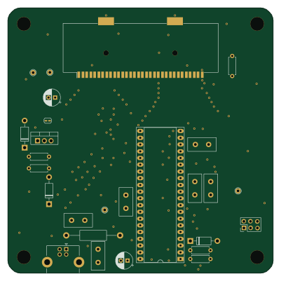 PIC
GB-CARTPP-DIY
Gekkio
100 × 100 mm22 parts2LCC-BY-4.0379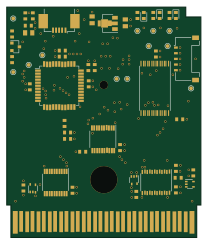 PIC
GB-LIVE32
51.4 × 61 mm46 parts4LCC-BY-4.0379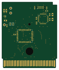 PIC
GB-CART256K-A
51.4 × 61 mm17 parts2LCC-BY-4.0379