
Osculati amperemetre sensor


About the Osculati amperemetre sensor PCB
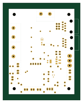
Osculati amperemetre sensor is an open source PCB design by mbouyer, published on GitHub under the BSD-2-Clause license. It is a 2-layer board measuring 62 × 52 mm, with 24 components from 15 distinct parts.
Other key parts include the LM4040DBZ-2.0, MCP6007-xSN, INA186A2 and LDL1117S50. By type, the board carries 6 capacitors, 4 ICs, 4 resistors, 3 connectors, 3 diodes and 2 fuses.
It belongs with the power & battery and sensors designs in this gallery.
From the project
12V battery monitoring
This project includes 2 boards for a service 12V Pb battery monitoring.
The main board monitors the battery voltage and current, using a microchip PAC1953 chip and a precision shunt resistor. It uses a pic18f with integrated CAN controller, and connects to a CAN bus network. Along with instant voltage and current values, the pic18f will be able to compute and report the battery SoC. As the PAC1953 has 3 channels, it will also be able to monitor other sources, like solar panel or the engine battery. The main battery will be monitored with an external, high current shunt resistor (100A/50mV)…
Main components on the Osculati amperemetre sensor
Osculati amperemetre sensor bill of materials (BOM)
24 components, 15 distinct parts.
| Qty | Part | Footprint | Refs |
|---|---|---|---|
| 1 | LM4040DBZ-2.0 | SOT-23 | U1 |
| 1 | MCP6007-xSN | SOIC-8_3.9x4.9mm_P1.27mm | U2 |
| 1 | INA186A2 | SOT-23-8_Handsoldering | U3 |
| 1 | LDL1117S50 | SOT-223-3_TabPin2 | U4 |
| 2 | Screw_Terminal_01x02 | MC24356 | J1, J2 |
| 1 | Screw_Terminal_01x03 | TerminalBlock_bornier-3_P5.08mm | J3 |
| 2 | MC011422 | R_0603_1608Metric_Pad0.98x0.95mm_HandSolder | F1, F2 |
| 2 | 5K | T93XA | RV1, RV2 |
| 3 | SMBJ16A | D_SMB | D1, D2, D3 |
| 4 | 100n | C_0805_2012Metric_Pad1.18x1.45mm_HandSolder | C1, C3, C4, C6 |
| 1 | 10µ | C_1210_3225Metric_Pad1.33x2.70mm_HandSolder | C2 |
| 1 | 10µ | C_0805_2012Metric_Pad1.18x1.45mm_HandSolder | C5 |
| 2 | 10K | R_1206_3216Metric_Pad1.30x1.75mm_HandSolder | R1, R2 |
| 1 | 4K7 | R_0805_2012Metric_Pad1.20x1.40mm_HandSolder | R3 |
| 1 | 12K | R_0805_2012Metric_Pad1.20x1.40mm_HandSolder | R4 |
Osculati amperemetre sensor design files
The KiCad project lives in the mbouyer/battery_monitor repository on GitHub; these links point at the commit this page was built from.
Osculati amperemetre sensor: common questions
How big is the Osculati amperemetre sensor PCB?
The Osculati amperemetre sensor measures 62 × 52 mm, has 2 copper layers and is 1.6 mm thick.
How many components are on the Osculati amperemetre sensor?
24 components, from 15 distinct parts. The full bill of materials is listed on this page.
Where can I download the Osculati amperemetre sensor design files?
From the mbouyer/battery_monitor repository on GitHub, which has the KiCad layout; the links under Design files point to each one.
Can I use the Osculati amperemetre sensor design in my own project?
Yes, under the terms of its BSD-2-Clause license, which mbouyer chose for the repository.
More boards in battery_monitor
Similar boards
Sensor smd
scottbez1
40 × 20 mm5 parts2LApache-2.04.2k
Sensors
StuckAtPrototype
15.2 × 9 mm14 parts4LApache-2.03.8k
EinkPDA screen
TalismanDesign
95 × 54 mm27 parts2LApache-2.02.0k
Stack chan
stack-chan
50 × 50 mm33 parts2LApache-2.01.7k
Display Carrier
AxxAxx
35.6 × 58.2 mm5 parts2LGPL-3.01.7k
Microphone
Mentra-Community
5.5 × 6.1 mm6 parts2LMIT1.2k